EasyManua.ls Logo

Sony HCD-RX33 User Manual

Sony HCD-RX33
42 pages
To Next Page IconTo Next Page
Page #1 background imageLoading...
Page #1 background image
HCD-RX33
AEP Model
UK Model
SERVICE MANUAL
MINI Hi-Fi COMPONENT SYSTEM
MICROFILM
HCD-RX33 is the tuner, deck, CD and
amplifier section in MHC-RX33.
— Continued on next page —
SPECIFICATIONS
Model Name Using Similar Mechanism HCD-G101
CD Mechanism Type CX3
Base Unit Type KSM-213BCM
Optical Pick-up Type KSS-213B/S-N
Model Name Using Similar Mechanism HCD-G101
DECK-A TK20FX-SW943-800
DECK-B TK20FX-SW943-800
CD
SECTION
TAPE
DECK
SECTION
Tape Transport
Mechanism Type
The following measured at AC 230 V 50 Hz;
DIN power output (Rated) 25 W + 25 W (6 at 1 kHz, DIN)
Continuous RMS power output (Reference)
35 W + 35W (6 at 1 kHz, 10% THD)
Outputs
PHONES (stereo phone jack) :
accepts headphones of 8 or more
SPEAKER : accepts impedance of 6 to 16
CD player section
System Compact disc and digital audio system
Laser Semiconductor laser (λ = 780 nm)
Emission duration: continuous
Laser output Max. 44.6 µW*
*This output is the value measured at a distance
of 200 mm from the objective lens surface on the
Optical Pick-up Block with 7 mm aperture.
Frequency response 20 Hz – 20 kHz (± 0.5 dB)
Wavelength 780 – 790 nm
Tape deck section
Recording system 4 -track 2 -channel stereo
Frequency response 60 – 13,000 Hz (± 3dB), using Sony
TYPE Ι cassette
Tuner section
FM stereo, FM/AM superheterodyne tuner
FM tuner section
Tuning range 87.5 – 108.0 MHz
Antenna FM lead antenna
Antenna terminal 75 unbalanced
Intermediate frequency 10.7MHz
AM tuner section
Tuning range 531 – 1,602 kHz
Antenna AM loop antenna
Antenna terminals External antenna terminal
Intermediate frequency 450 kHz
Question and Answer IconNeed help?

Do you have a question about the Sony HCD-RX33 and is the answer not in the manual?

Sony HCD-RX33 Specifications

General IconGeneral
Power Output100 W
RMS Output Power50 W
Audio Channels2.0
CD PlayerYes
TunerFM/AM
Cassette DeckYes
BluetoothNo
USB PlaybackNo
Remote ControlYes
Weight5.5 kg
TypeMini System

Summary

Servicing Notes and Precautions

Handling Optical Pick-Up Block

Precautions for handling the optical pick-up block and flexible boards during repair.

Laser Diode Emission Check

Guidance on safely checking the laser diode emission from the optical pick-up.

Safety-Related Component Warnings

Critical warnings regarding hazardous radiation, chip component replacement, and soldering.

Section 1 General

Location of Parts and Controls

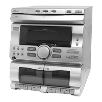
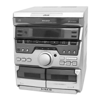
Identifies and labels all external controls, buttons, and display elements of the unit.

Section 3 Mechanical Adjustments

Section 4 Electrical Adjustments

Deck Section Electrical Adjustments

Procedures for Azimuth and Tape Speed adjustments for both decks.

Electrical Adjustments (Continued)

Record/Playback Head Azimuth Adjustment

Detailed procedure for adjusting the azimuth of the record/playback head for optimal audio quality.

AM Tuning Voltage and Tracking Adjustment

Procedures for adjusting AM tuning voltage and tracking using test equipment.

FM Tuned Level Adjustment

Procedure to adjust FM tuned level by observing the TUNED indicator.

Tape Speed Adjustment

Steps to adjust tape speed using a frequency counter and test tape.

CD Section Adjustments

CD Section Checks and Adjustments

Procedures for RF level check, focus bias, and notes on focus gain adjustment.

Section 5 Diagrams (Continued)

Block Diagram - Deck Section

Block diagram illustrating the signal flow and components of the deck section.

Block Diagram - Tuner/CD Section

Block diagram illustrating the signal flow and components of the tuner and CD sections.

Correction Sheet

Capacitor Part Number Corrections

Lists specific capacitor part number corrections with incorrect and correct values.

Diode and IC Part Number Corrections

Lists specific diode and IC part number corrections with incorrect and correct values.

Related product manuals