7
Locations and Functions of Parts
Front Panel
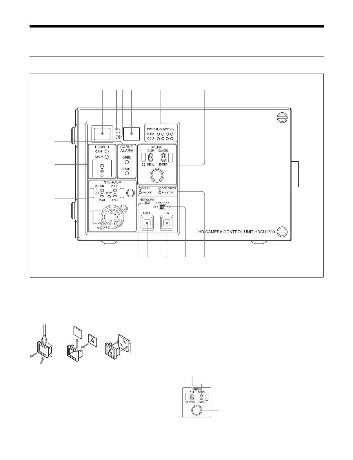
a Red tally indicator
Lights in red when this unit receives a red tally signal. When
the CALL button on the MSU-1000 series Master Setup Unit,
RCP-1000 series Remote Control Panel, etc., is pressed, this
indicator will go out if previously lit, and light up if previously
off. You can attach the supplied number plate here.
b Yellow tally indicator
Lights in yellow when this unit receives a yellow tally signal.
c Green tally indicator
Lights in green when this unit receives a green tally signal.
d CCU number display
The camera number set via the CCU menu is displayed.
e Optical signal reception status indicator
This indicates the camera and CCU’s optical signal reception
status when performing optical transmissions.
When the two lamps on the right (green) are lighted:
Reception status is excellent.
When the second lamp from the right (green) is lighted:
Reception status is good.
When the second lamp from the left (yellow) is lighted:
Reception status is low.
When the lamp on the left (red) is lighted: Reception status
is at the lowest level.
f MENU control block
8
9
qa
24
7
qs
13
qd qf
65
0
DISP/MENU (display/menu) lever and indicator
CANCEL/ENTER lever
CONTROL knob


 To Next Page