18
• Outputs analog component signals or analog composite
signals through a VDA-C board.
When you use either the VDA-A board or the VDA-B board,
insert the EN-B board in the corresponding expansion slot on
the front of the HDCU2000/2500. When either the VDA-A
board or the VDA-B board is installed, you can insert the VDA-
C board in an expansion slot on the rear panel of the
HDCU2000/2500. Don’t insert any board in the corresponding
expansion slot on the front of the HDCU2000/2500.
For details on installation, contact a Sony service or sales
representative.
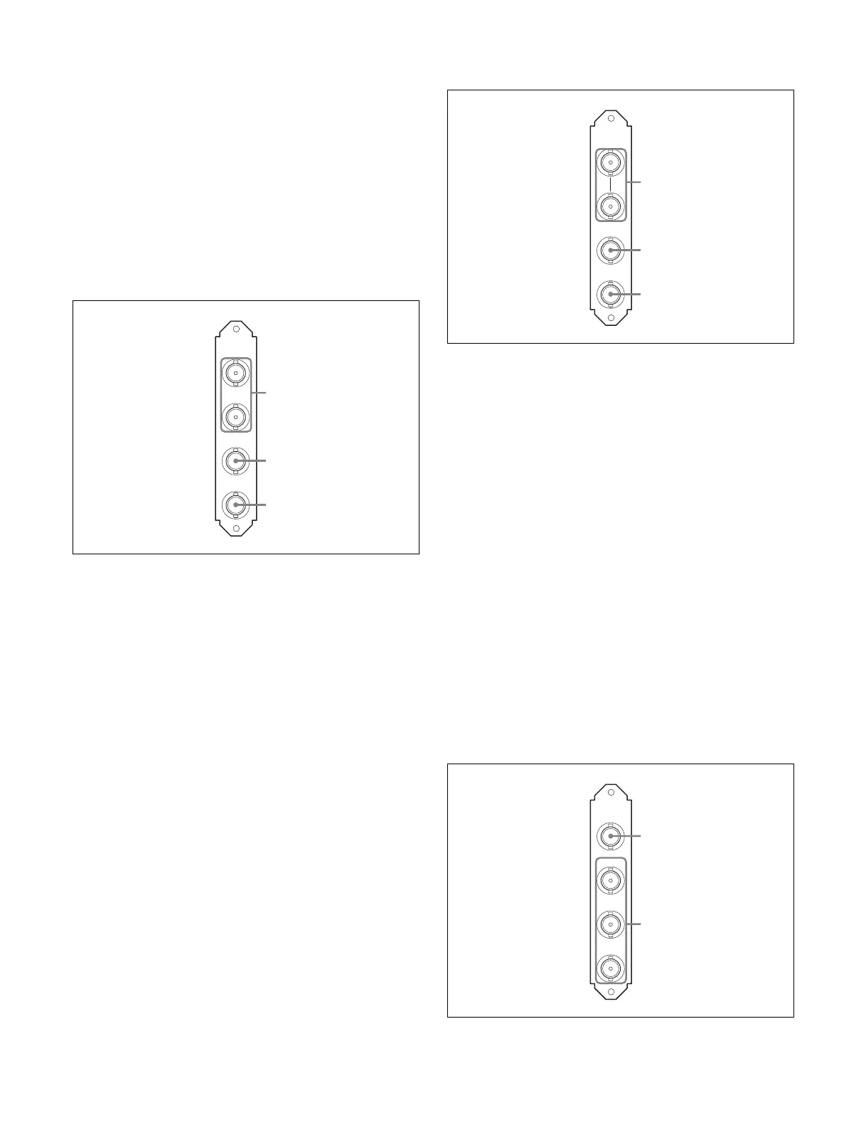
VDA-A Board
a VBS 1, 2 (composite video output 1, 2) connectors
(BNC-type)
The signal from the video camera may be output as two
analog composite signals.
b PIX OUT (picture monitor output) connector (BNC-
type)
Outputs the video signal for a picture monitor selected with the
PICTURE MONITOR button of an RCP-1000 series Remote
Control Panel or MSU-1000 series Master Setup Unit.
Character signals or marker signals can be superimposed on
the video signal output through this connector.
For details on these operations, refer to the Master Setup Unit
or Remote Control Panel manuals.
c WF OUT (waveform monitor output) connector (BNC-
type)
Outputs the video signal for a waveform monitor selected with
the WF MONITOR button of an RCP-1000 series Remote
Control Panel or MSU-1000 series Master Setup Unit.
For details on these operations, refer to the Master Setup Unit
or Remote Control Panel manuals.
VDA-B Board
a FRAME REF IN, OUT (frame reference input/output)
connectors (BNC-type)
Input an HD tri-level reference sync signal or SD reference
sync signal (black burst signal) for the sequence-lock between
the camera control units, to the upper of the two connectors.
The input signal is output from the lower connector as is (loop-
through output).
When not using the OUT connector, terminate it at 75 ohms.
b PIX OUT (picture monitor output) connector (BNC-
type)
Outputs the video signal for a picture monitor selected with the
PICTURE MONITOR button of an RCP-1000 series Remote
Control Panel or MSU-1000 series Master Setup Unit.
For details on these operations, refer to the Master Setup Unit
or Remote Control Panel manuals.
c WF OUT (waveform monitor) connector (BNC-type)
Outputs the video signal for a waveform monitor selected with
the WF MONITOR button of an RCP-1000 series Remote
Control Panel or MSU-1000 series Master Setup Unit.
For details on these operations, refer to the Master Setup Unit
or Remote Control Panel manuals.
VDA-C Board
VDA-A
1
2
PIX
OUT
WF
OUT
VBS
1
2
3
FRAME
REF IN
PIX
OUT
WF
OUT
OUT
VDA-B
1
2
3
VBS
R/R-Y
G/Y
B/B-Y
VDA-C
1
2


 To Next Page