9
Locations and Functions of Parts
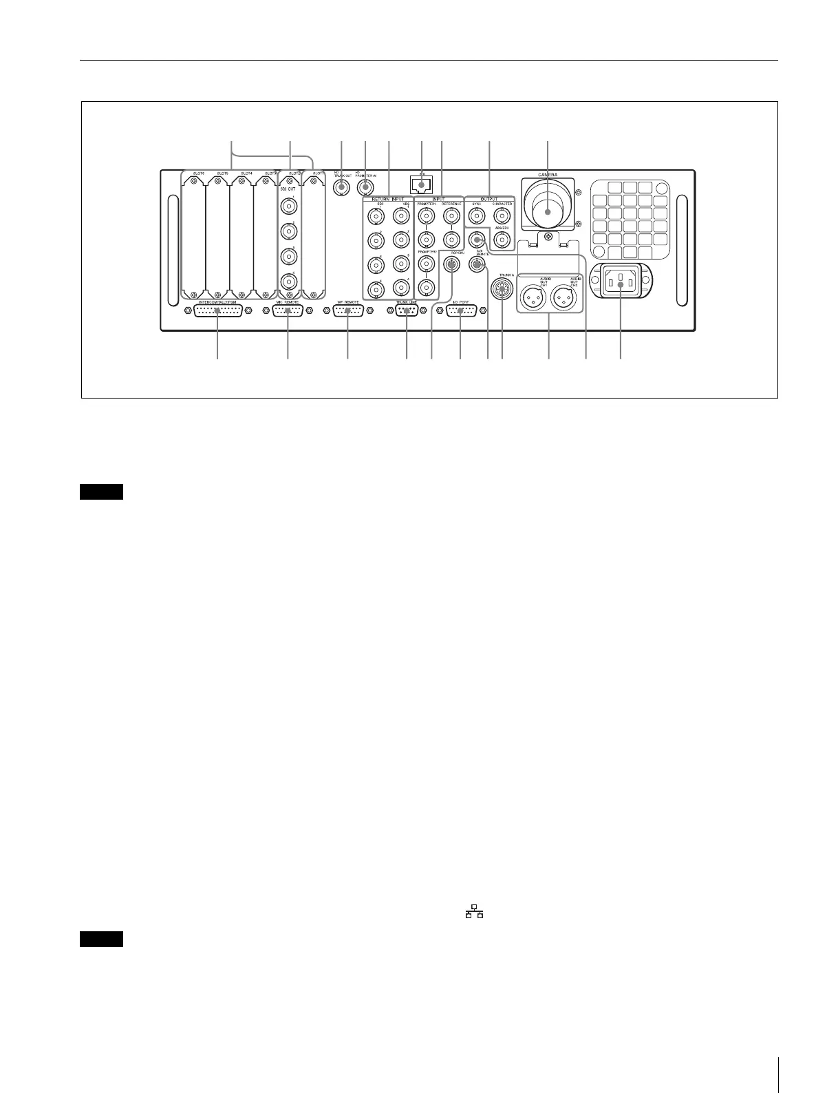
HDCU2080 Rear Panel
a Expansion slots
For installation of an optional HKCU2007 3G/HD SDI Output
Expansion Unit, HKCU1001 SD Encoder Unit, or HKCU1003
Multi Interface Unit.
Note
The HDCU2080 does not support 3G digital optical output.
For details on installation, contact a Sony service or sales
representative.
b HD/SD SDI OUTPUT (SDI output connectors) area
(BNC-type)
The signal from the video camera may be output as two HD-
SDI signals or two SD-SDI signals. The signals output from the
OUTPUT3 and OUTPUT4 connectors can be superimposed
character and marker signals.
Signals of the same format are output from the SDI 1 and SDI
2 connectors; similarly, signals of another format can be
output from the SDI 3 and SDI 4 connectors.
For details on settings, contact a Sony service or sales
representative.
c HD TRUNK OUT connector (BNC-type)
When an HD TRUNK function-compatible camera is
connected to the CAMERA connector, the HD-SDI signal input
to the camera’s HD TRUNK IN connector is output from the
HD TRUNK OUT connector.
d HD PROMPTER IN connector (BNC-type)
When an HD prompter function-compatible camera is
connected to the CAMERA connector, the HD-SDI signal input
to the HD PROMPTER IN connector is output from the
camera’s SDI connector.
Note
Input an HD-SDI signal with a frequency synchronized to the
camera control unit.
e RETURN INPUT area
1 SDI 1 to 4 (HD/SD-SDI return video 1/2/3/4 input)
connectors (BNC-type)
Four different HD/SD-SDI return video input signals may be
received independently.
The selection of RET 1, 2, 3, or 4 is made by the return switch
of the video camera.
The type of input signal on RET 1, 2, 3, and 4 may be set
individually using the setup menu, or using the MSU-1000
series Master Setup Unit. The aspect ratio can also be
selected for an SD signal.
For details on the setup menu, contact a Sony service or sales
representative.
Refer also to the Master Setup Unit manual.
2 VBS 1 to 4 (VBS return video 1/2/3/4 input)
connectors (BNC-type)
Four different VBS return video input signals may be received
independently.
The selection of RET 1, 2, 3, or 4 is made by the return switch
of the video camera.
The type of input signal on RET 1, 2, 3, and 4 may be set
individually using the setup menu, or using the MSU-1000
series Master Setup Unit.
An aspect ratio may also be selected for SD signals.
For details on setup menu operations, contact a Sony service
or sales representative.
Refer also to the Master Setup Unit manual.
f (LAN) connector (RJ-45 8-pin)
For LAN connection. Connect a LAN HUB (10BASE-T/
100BASE-TX), using a LAN cable (shielded type of category 5
or more).
8
ql
9
0
257
qa
13
qs qd
qf qkqjqhqg
6
w;
4


 To Next Page