2-19-2. IF-1371 Board
Preparation
1. Remove the top cover. (Refer to “2-2. Top Cover”)
2. Remove the optical cable. (Refer to step 1 in “2-4-1. LEMO Connector Assembly”)
3. Remove the ENC assembly. (Refer to “2-19-1. ENC Assembly”)
Procedure
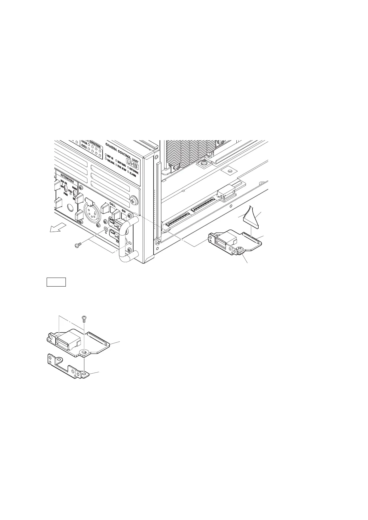
1. Remove the IF-1371 board.
(1) Remove the two screws, then remove the IF-1371 board assembly.
(2) Disconnect the fine-wire coaxial cable from the connector (CN001) on the IF-1371 board.
Front side
P2.6 x 5
(a)
(b)
Yellow
Fine-wire coaxial cable
IF-1371 board assembly
CN001
Note
When attaching the IF-1371 board assembly, tighten the screws in the following sequence: (a), (b).
2. Remove the two screws, then remove the IF-1371 board.
B3 x 5
IF-1371 board
Board bracket (IF)
3. Install the removed parts by reversing the steps of removal.
HDCU3500/HDCU5500
2-55

 Loading...