7
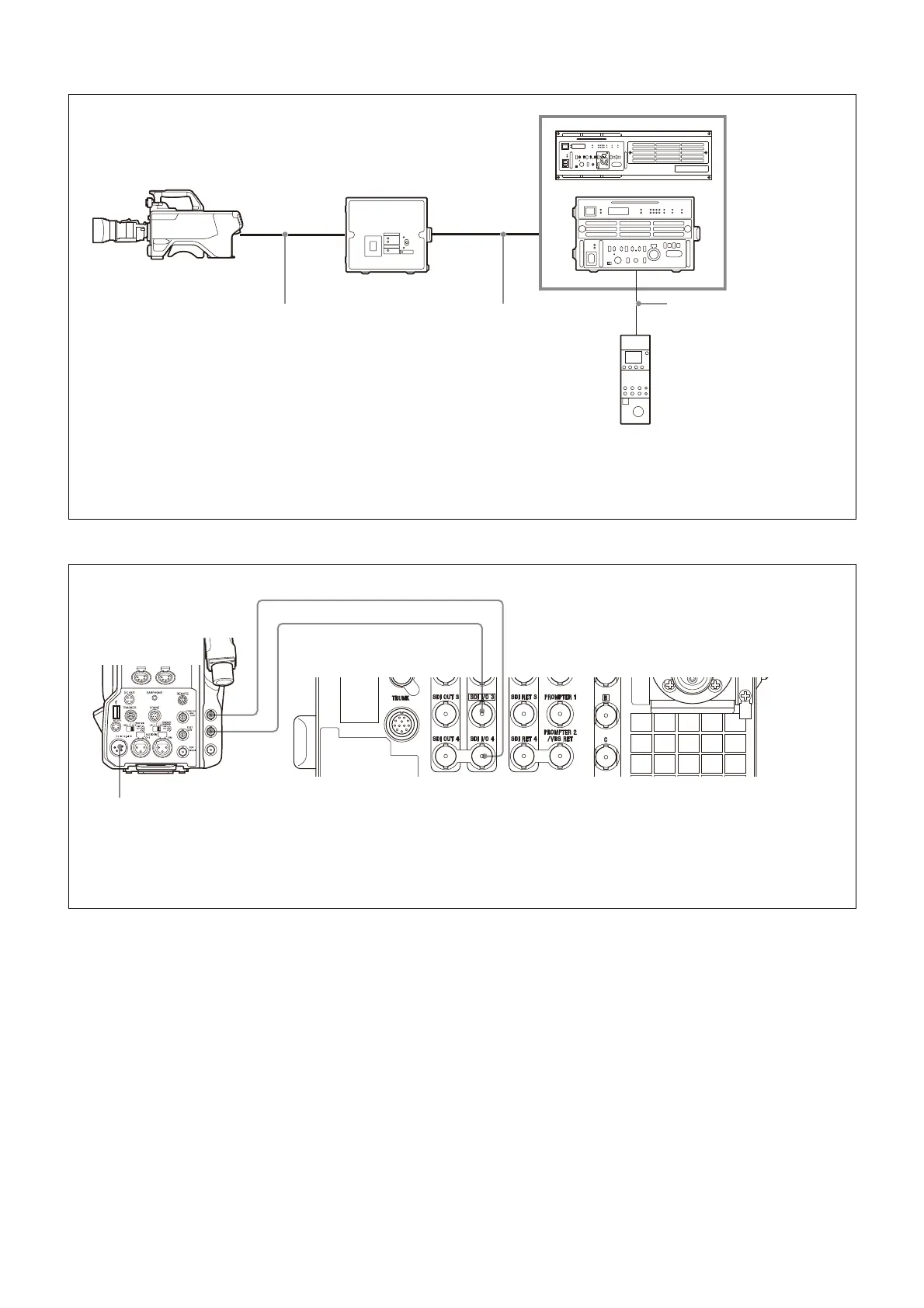
Connection example (single-mode fiber connection)
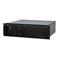
Connection example (coax connection)
HDCU5000
b) c)
HDC3500/3100
HDC2000 series
a)
Color Camera
Optical fiber cable Single-mode fiber cables
d)
(2)
RCP-3000/1000 series
Remote Control Panel
HDCE-100
Camera Extension
Adaptor
a) HDC2000 series: HDC2000/2580/2500/2400/1700
b) Install the HKCU-SM50 Single Mode Fiber Connector Kit.
c) Set the transmission type using the following menu item on the HDCU5000/5500/3500.
SYSTEM CONFIG t <CAMERA I/F> t CABLE TYPE t SINGLE-MODE FIBER
d) Signal transfer up to a maximum of 10 km is possible. However, the actual transfer distance may vary depending on the system configuration of the
cameras and the type of single-mode optical fiber cables used.
CCA-5 cable
HDCU5500/3500
b) c)
or
INCOM
INTERCOM 1
PROD
LEVEL
REAR
FRONT
MIC
ON
OFF ENG
INCOM
INTERCOM 2
PROD
LEVEL
REAR
FRONT
MIC
ON
OFF ENG
HDCU3500
b)
SDI 1
DC power source
a)
BNC cable (HD SDI)
a) A dedicated power supply (external DC power source) for the camera is required. Power is not supplied from the camera control unit.
b) Configure the following menu settings.
• Set SYSTEM CONFIG t <CAMERA I/F> t CABLE TYPE to COAX.
• Set SYSTEM CONFIG t <VIDEO I/O> t SDI-I/O 3 t SIGNAL to HD TRUNK.
• Set SYSTEM CONFIG t <VIDEO I/O> t SDI-I/O 4 t SIGNAL to HD PROMPTER.
BNC cable (HD SDI)
SDI 2
SDI I/O 3 SDI I/O 4