UFOELK - 2/21/2018 5:23 PM
HT-RT3
9
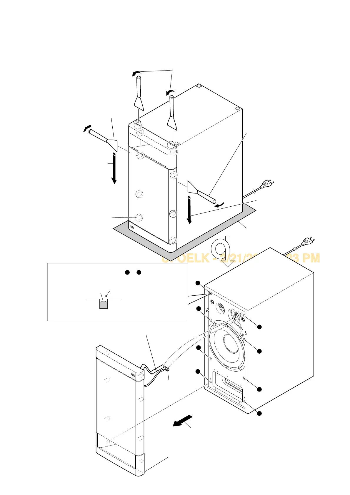
Note: Follow the disassembly procedure in the numerical order given.
2-2. FRONT PANEL SECTION
total eight bosses
5 Remove the front panel section
in the direction of the arrow.
6 CN3000 (5P)
7 wire (flat type) (20 core) (CN5009)
8 front panel section
Note 3: When installing the front panel section,
remove the used glue and use a new
glue to fix the front panel section.
– Front view –
1 Insert a jig in two notches of bottom of the unit,
and lift the front panel section a little.
3 All bosses are removed
while moving jig in the
direction of the arrow,
and front panel section
is removed.
3 All bosses are removed
while moving jig in the
direction of the arrow,
and front panel section
is removed.
4
2 Insert the jig into a space and
raise front panel section.
Note 2: When using a jig,
please work so as not
to injure front panel
section and cabinet.
2 Insert the jig into a space and
raise front panel section.
Note 2: When using a jig,
please work so as
not to injure front panel
section and cabinet.
Note 1: Please spread a sheet under a
unit not to injure cabinet.
– Bottom view –
a
b
c
d
e
f
g
h
Ɣ*OXHVHWWLQJ
Fill in 2/3 of the bosses hole (step A to H) on the
cabinet with new glue. Ensure the front panel section
is fully inserted to cabinet.
h
a
glue
bosses hole
Glue type: Ethylene Vinyl Acetate Emulsion Adhesives