HVR-M10C/M10E/M10J/M10N/M10P/M10U
2-1 2-2
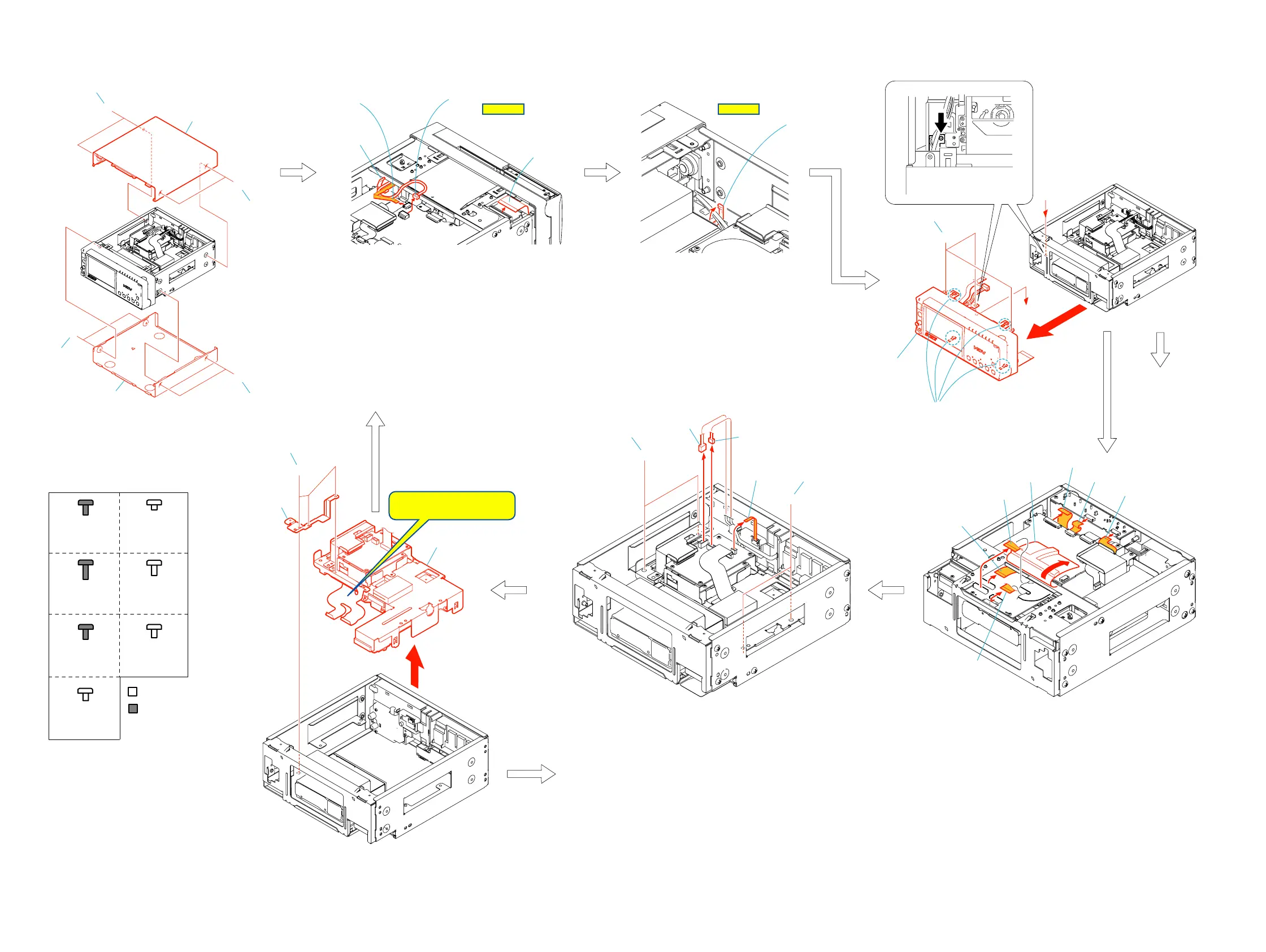
2-1. DISASSEMBLY
The following flow chart shows the disassembly procedure.
2. DISASSEMBLY
2
3
1
7
6
5
3
2
4
1
2
4
3
1
2
5
3
1
1
4
3
2
1
Front panel section
(See page 2-5)
Main frame section-1 (See page 2-3)
Main frame section-2 (See page 2-5)
2
1
4
6
5
3
1
Two screws (M3
×
6)
2
Two screws (M3
×
6)
3
Cabinet (upper)
4
Two screws (M3
×
6)
5
Two screws (M3
×
6)
6
Cabinet (lower)
1
Open the clamper
2
FFC-094 Flexible flat cable (8P)
3
Harness (HP-146)
4
FFC-093 Flexible flat cable (50P)
1
Open the clamper
A
D
D
A
I
A
I
A
1
Three screws (M2x3) silver
2
Four claws
3
Front panel section
a
a
1
Peel the sheet (SW-VA)
2
FP-230 flexible board (22P)
3
FP-230 flexible board (30P)
4
FP-098 flexible board (28P)
5
FP-090 flexible board (10P)
6
FP-096 flexible board (12P)
7
FP-095 flexible board (28P)
1
FFC-095 Flexible flat cable (6P)
2
Battery terminal board (4P)
3
DC-IN connector (3P)
4
Two screws (M3x6) silver
5
Two screws (M3x6) silver
1
Three screws (M2x3) silver
2
Ground plate (HP)
3
Main frame section
Screw
M3x6
2-059-756-01
Screw
M3x8
3-077-331-41
Silver
Black
Screw
M3x6
3-077-331-21
Screw
M1.4x1.5
3-059-718-01
A
D
B
C
EF
I
Screw
M2x5
7-681-000-00
Tapping screw
M2x5
3-080-206-21
Screw
M2x3
3-080-202-21
Note:
Be very careful not to
damage the flexible board.
HELP 01 HELP 02
A
C
B
Ver 1.2 2005. 09





 To Next Page