
K
kdavisSep 23, 2025
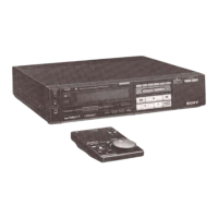
What to do if my Sony VCR cannot playback?
- TTimothy PadillaSep 23, 2025
If you cannot playback a tape on your Sony VCR, rewind the tape if it has reached its end.
What to do if my Sony VCR cannot playback?
If you cannot playback a tape on your Sony VCR, rewind the tape if it has reached its end.
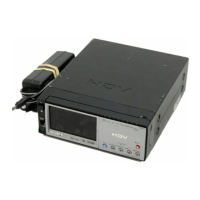
Why are there horizontal lines on my Sony HVR-M10C image?
Horizontal lines or blurred/missing images on your Sony VCR could be due to a damaged tape or dirty video heads. Try removing the cassette and inserting another one. If that doesn't work, clean the video heads using the supplied cleaning cassette.
Why is the audio noisy on my Sony HVR-M10C VCR?
Noisy audio on your Sony VCR can be caused by a damaged tape or dirty video heads. Try removing the cassette and inserting another one. If the problem persists, clean the video heads using the supplied cleaning cassette.
What to do if my Sony HVR-M10C VCR won't operate?
If your Sony VCR unit won't operate even after turning it on, it could be due to moisture condensation or the cassette not being inserted correctly. Eject and reinsert the cassette straight. Disconnect the power supply (battery or AC adapter) and then reconnect it after about 1 minute. If it still doesn't work, use a sharp-tipped ballpoint pen to press the RESET button (note that this will clear all settings).
How to fix a Sony VCR remote that is not working?
If the supplied wireless Remote Commander for your Sony VCR isn't working, set [REMOTE CTRL] on the [OTHERS] menu to [ON].
Why is there no image on the monitor when editing dubbing on my Sony HVR-M10C VCR?
If you are editing dubbing and the monitor does not display any image when an i.LINK cable is connected to your Sony VCR, use the correct setting for [VCR HDV/DV] on the [IN/OUT REC] menu in accordance with the equipment to be connected.
Why is the image distorted when playing tapes on my Sony HVR-M10C VCR?
If the image loses color or is distorted when you play back a tape on a television set or monitor connected to your Sony VCR, connect the unit to a television set or monitor that is compatible with its [50i/ 60i SEL] format. Set [50i/60i SEL] in the [OTHERS] menu, according to the signal-format.
Why doesn't the CHG lamp light when charging my Sony HVR-M10C?
If the CHG (charge) lamp does not light while the battery is charging on your Sony VCR, correctly reinstall the battery. The battery is possibly already fully charged.
Why is the CHG lamp flashing on my Sony HVR-M10C?
If the CHG (charge) lamp on your Sony VCR is flashing while the battery is charging, correctly reinstall the battery. If it continues to flash, remove the power cord from the AC outlet and contact Sony Customer Service, as the battery is likely faulty.
What to do if Sony HVR-M10C VCR turns off immediately even with battery?
If there is enough remaining battery power but the power turns off immediately on your Sony VCR, fully recharge the battery. The remaining battery power will then be displayed correctly. The issue could be due to a faulty battery power indication or improper charging.
Records changes made to the service manual.
Highlights critical components for safe operation that require specific replacement parts.
Outlines the overall disassembly procedure using a flowchart.
Shows the physical locations of various circuit boards within the unit.
Shows the overall block diagram of the unit's signal flow, part 1 of 5.
Shows the frame schematic diagrams for the unit, part 1 of 2.
Lists and provides access to various schematic diagrams of the unit's circuits.
Provides exploded views of the unit's sections for identifying parts.
Lists electrical components used in the unit.
Explains preparations and procedures before starting adjustments, including EVR data rewriting.
Provides guidance on checking, adjusting, and replacing mechanical parts.
Explains how to access and use the service mode.