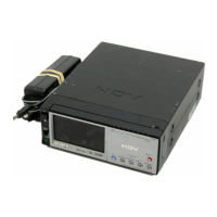
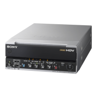
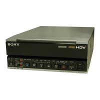
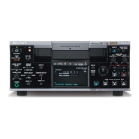
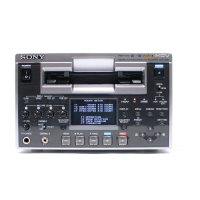
HVR-M10U
US Model
Canadian Model
HVR-M10E
AEP Model
HVR-M10C
Chinese Model
HVR-M10N/M10P
E Model
HVR-M10J
Japanese Model
SERVICE MANUAL
DIGITAL HD VIDEOCASSETTE RECORDER
Link
SERVICE NOTE
DISASSEMBLY
BLOCK DIAGRAMS
FRAME SCHEMATIC DIAGRAMS
SCHEMATIC DIAGRAMS
PRINTED WIRING BOARDS
REPAIR PARTS LIST
SPECIFICATIONS
ADJUSTMENT
SERVICE NOTE
DISASSEMBLY
BLOCK DIAGRAMS
FRAME SCHEMATIC DIAGRAMS
SCHEMATIC DIAGRAMS ADJUSTMENT
PRINTED WIRING BOARDS
REPAIR PARTS LIST
SPECIFICATIONS
Link
Revision History
Revision History
Ver. 1.5 2006. 10
How to use
Acrobat Reader
How to use
Acrobat Reader
Sony EMCS Co.
2006J1600-1
©2006.10
Published by Kohda TEC
9-876-852-11
HVR-M10C/M10E/M10J/M10N/M10P/M10U
HVR-M10C/M10E/M10J
M10N/M10P/M10U
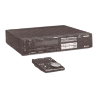
RMT-843
Photo : HVR-M10E
Z (Z311) MECHANISM
• INSTRUCTION MANUAL is shown at the end of this document.
• Reference number search on printed wiring boards is available.
• TO TAKE OUT A CASSETTE WHEN NOT EJECT (FORCE EJECT)