HVR-M10C/M10E/M10J/M10N/M10P/M10U
2-5 2-6
MR-048
I
E
E
E
F
2
1
2
3
4
5
1
3
4
6
5
7
1
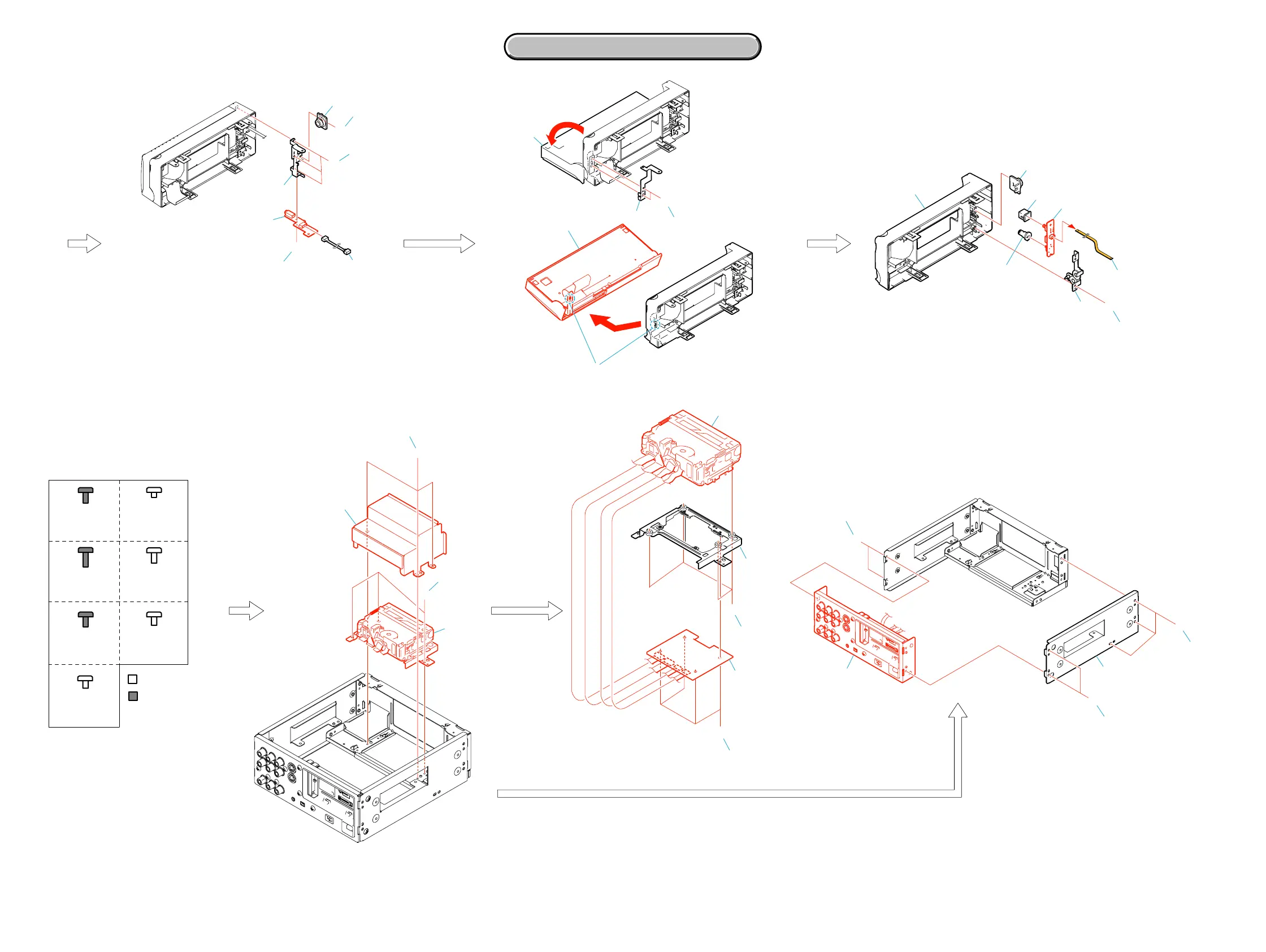
Harness (HP-146)
2
Screw (M2x5) silver
3
Damper
4
Three tapping screws (M2x5) black
5
Screw (M2x3) silver
6
Front sub chassis
7
HP-139 board
5
4
1
6
7
8
2
3
1
Lean the control panel section
in the direction of an arrow a .
2
Two tapping screws (M2x5) black
3
Ground plate (R)
4
Dowel
5
Remove the control panel section
in the direction of an arrow b .
1
Tapping screw (M2x5) black
2
Fulcrum plate (front L)
3
Damper
4
Front panel assembly
5
FFC-094 Flexible flat cable (8P)
6
(Power) button
7
(HP VOL) knob
8
PW-129 board
1
1
3
4
5
2
2
3
4
I
I
I
B
1
Three screws (M2x3) silver
2
Cover (MD)
3
Three screws (M2x3) silver
4
Mechanism deck,
MD frame assembly
1
Four screws (M2x3) silver
2
MR-048 board
3
Four screws (M1.4x1.5) silver
4
MD frame assembly
5
Mechanism deck
D
D
D
1
3
4
5
2
1
Three screws (M3x6) silver
2
Two screws (M3x6) silver
3
Side plate (L)
4
Two screws (M3x6) silver
5
Rear panel section
C
B
Screw
M3x6
2-059-756-01
Screw
M3x8
3-077-331-41
Silver
Black
Screw
M3x6
3-077-331-21
Screw
M1.4x1.5
3-059-718-01
A
D
B
C
EF
I
Screw
M2x5
7-681-000-00
Tapping screw
M2x5
3-080-206-21
Screw
M2x3
3-080-202-21
a
b
2. DISASSEMBLY
2. DISASSEMBLY






 To Next Page