ICD-UX522F/UX523F
5
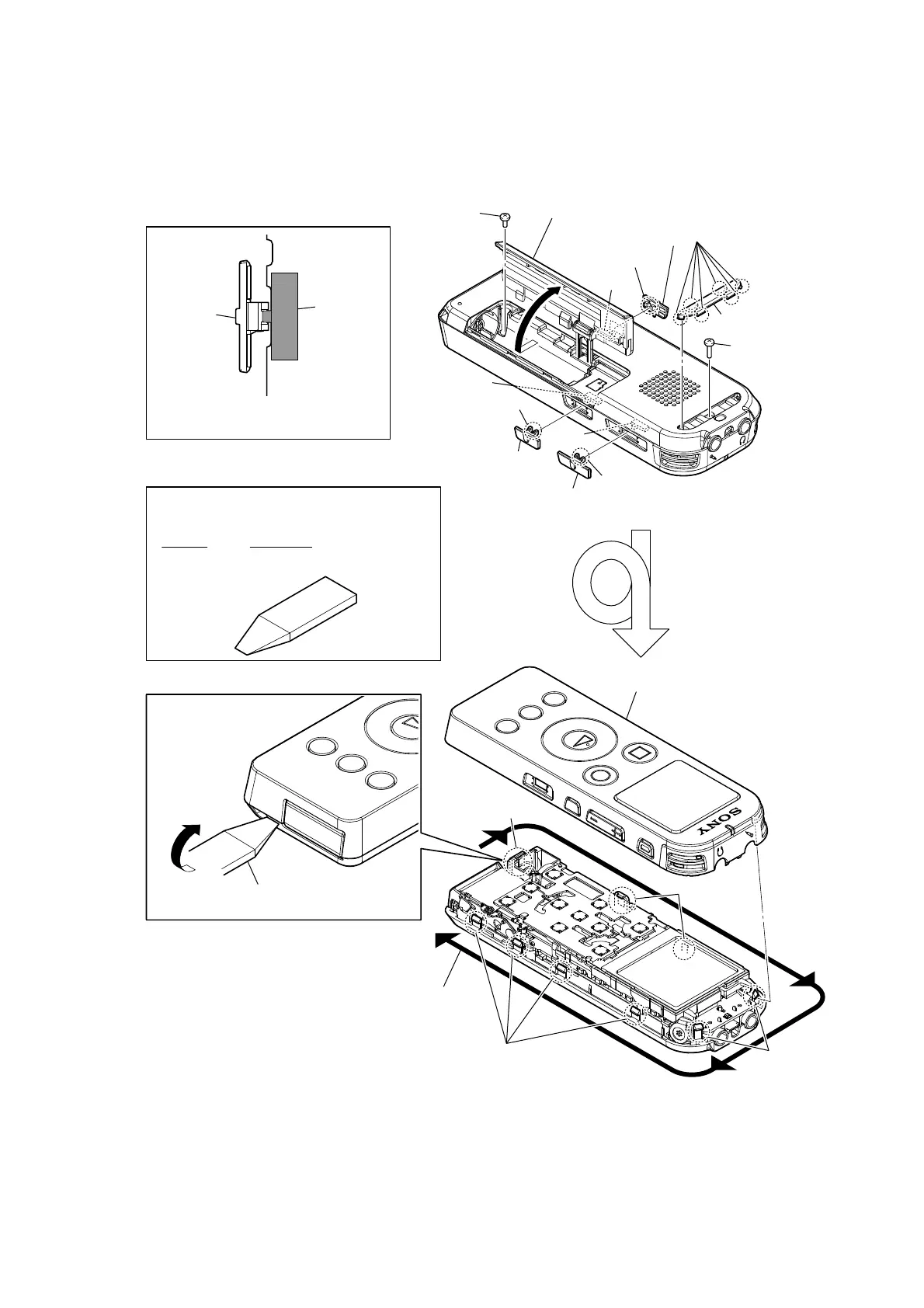
Note: Follow the disassembly procedure in the numerical order given.
2-2. CASE (F) ASSY
0
Insert the jig in the space between the case
(F) assy and the case (R) assy and remove.
7 screw
(PTP1.4)
9 screw
8 Open the battery case lid.
1 two claws
3 two claws
2 knob (DPC)
knob
switch
switch
switch
switch
1 two claws
qa two claws
qa two claws
qa four claws
qa claw
5 six claws
– Rear top view –
– Front top view –
4 knob (power)
6 foot (case)
2 knob (DPC)
Note: When installing each knob, match the
position of switches and each knob.
qs Remove all claws while rounding in outer.
qd case (F) assy
JIG
When disassembling the set, use the following jig.
Part No. Description
9-913-402-33 Tool for Disassembly