EasyManua.ls Logo

Sony ICF-9740W Service Manual

Sony ICF-9740W
11 pages
To Next Page IconTo Next Page
Page #1 background imageLoading...
Page #1 background image
SPECIFICATIONS
Frequency
range:
FM87.5—108
MHz
(3.43—-2.78m)
AM530—1,605
kHz
(566—187m)
Antennas:
FM:
AC
power
cord
antenna.
External
antenna
terminals
(75
ohms)
'
;
AM:
Built-in
ferrite
bar
antenna
Speaker:
.
Approx.
16cm
(63/,
inches)
dia.
Power
output:
2W
(at
10%
harmonic
distortion)
Power
requirements:
120V
ac,
60
Hz
Dimensions:
Approx.330x232x136mm
(w/h/d)
(13x9%x57/,
inches)
Incl.
projecting
parts
and
controls
Weight:
Approx.
2.2kg
(4
lb
13
oz)
ATTENTION
AU
COMPOSANT
AYANT
RAPPORT
A
LA
SECURITE!
LES
COMPOSANTS
IDENTIFIES
PAR
UNE
TRAME
ET
UNE
MARQUE
SUR
LES
DIAGRAMMES
SCHE-
MATIQUES,
LES
VUES
EXPLOSEES
ET
LA
LISTE
IES
PIECES
SONT
CRITIQUES
POUR
LA
SECURITE
DE
FONCTIONNEMENT.
NE
REMPLACER
CES
COMPOSANTS
QUE
PAR
DES
PIECES
SONY
DONT
LES
NUMEROS
SONT
DONNES
DANS
CE
MANUEL
OU
DANS
LES
SUPPLEMENTS
PUBLIES.
PAR
SONY.
MICROFILM
SAFETY-RELATED
COMPONENT
WARNINGI!!
COMPONENTS
IDENTIFIED
BY
SHADING
AND
MARK
ON
THE
SCHEMATIC
DIAGRAMS,
EXPLODED
VIEWS
AND
IN
THE
PARTS
LIST
ARE
CRITICAL
TO
SAFE
OPERATION.
REPLACE
THESE
COMPONENTS
WITH
SONY
PARTS
WHOSE
PART
NUMBERS
APPEAR
AS
SHOWN
iN
THIS
MANUAL
OR
IN
SUPPLEMENTS
PUBLISHED
BY
SONY.
+

Other manuals for Sony ICF-9740W

Question and Answer IconNeed help?

Do you have a question about the Sony ICF-9740W and is the answer not in the manual?

Sony ICF-9740W Specifications

General IconGeneral
Tuning SystemAnalog
Tuning BandsAM/FM
Frequency Range (AM)530 - 1605 kHz
Frequency Range (FM)87.5 - 108 MHz
Power SourceAC
SpeakerBuilt-in
Output Power0.5 W

Summary

Specifications

Technical Specifications

Lists frequency ranges, antennas, speaker, power output, power requirements, dimensions, and weight.

Safety Component Warning

Highlights critical safety components identified by shading and mark A for safe operation.

Outline and Block Diagram

Block Diagram

Illustrates the functional blocks of the FM/AM 2-band radio receiver.

Disassembly and Removal Procedures

Component Removal

Details the steps and hardware required for removing the rear panel, main board, and volume board.

Dial Cord Stringing Instructions

Dial Cord Length and Stringing

Provides instructions and diagrams for measuring and correctly stringing the dial cord.

Adjustment and Alignment Procedures

FM/AM Alignment Steps

Details adjustments for FM/AM tracking, frequency coverage, and IF stages using test equipment.

Diagrams and Layouts

Mounting Diagram and Component Layouts

Illustrates physical component placement and semiconductor lead orientations on the main board.

Schematic Diagrams

Presents detailed circuit schematics for the main and volume boards.

Exploded View

Exploded View of Components

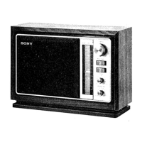
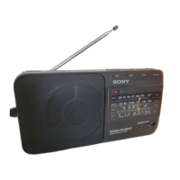
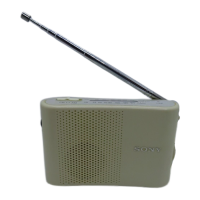
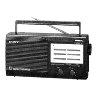
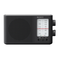
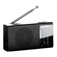
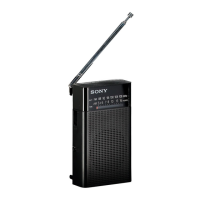
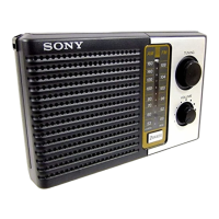
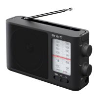
Visual representation of the radio's components for identification and assembly.

Parts and Accessories

Electrical Component Part Numbers

Detailed list of semiconductors, passive components, and hardware with part numbers.

Accessories and Packing Materials

Lists items included with the radio, such as manuals, labels, and packaging.

Resistor Values and Hardware

Lists resistor values and defines screw, nut, washer, and retaining ring types.

Safety Leakage Test

AC Leakage Testing Procedure

Details how to perform safety checks for AC leakage on exposed metal parts.

Related product manuals