Do you have a question about the Sony ICF-SW7600G and is the answer not in the manual?
Describes the procedure for powering the unit on and off for servicing purposes.
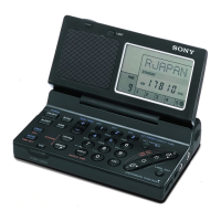
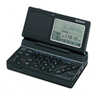
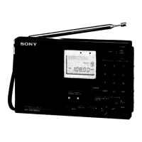
Details the location and purpose of all front and rear panel controls.
Step-by-step guide for setting the unit's internal clock.
Instructions on how to adjust the MW channel spacing.
Explains how to tune stations by directly entering their frequencies.
Guide on how to tune stations using manual frequency adjustment.
Describes the automatic station scanning feature.
Instructions for storing and recalling preset stations.
Procedure for removing the rear cabinet cover for access.
Details the steps for adjusting the AM and FM radio sections.
Provides pin configurations and block diagrams for integrated circuits.
Illustrates the layout of components on the printed circuit boards.
Presents the detailed circuit schematics for the radio.
Shows the lead configurations for semiconductor components.
Diagram showing the assembly of the radio's cabinet components.
Diagram illustrating the assembly of the radio's chassis components.
Lists diodes, ICs, capacitors, and transistors with part numbers.
Lists resistors, switches, variable resistors, and transformers with part numbers.
Lists miscellaneous items and accessories with part numbers.
| SSB Reception | Yes |
|---|---|
| Synchronous Detection | Yes |
| Headphone Jack | Yes |
| FM Frequency Range | 76 - 108 MHz |
| SW Frequency Range | 1602 kHz - 29.999 MHz |
| LW Frequency Range | 153 - 513 kHz |
| MW Frequency Range | 531 - 1602 kHz |
| Bands | FM, MW, SW, LW |
| Antenna | Telescopic antenna for FM/SW, built-in ferrite bar antenna for LW/MW |
| Power Supply | 4 x AA batteries or AC adapter |
| Speaker | 77 mm diameter |
| Dimensions | 190 x 118 x 38 mm |
| Features | Sleep Timer |
| Frequency Range | LW, MW, SW, FM |
| Memory | 100 presets |