EasyManua.ls Logo

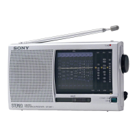
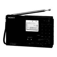
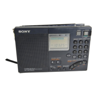
Sony ICF-SW35 Service Manual

Sony ICF-SW35
22 pages
To Next Page IconTo Next Page
Page #1 background imageLoading...
Page #1 background image
– 1 –
SERVICE MANUAL
US Model
Canadian Model
AEP Model
E Model
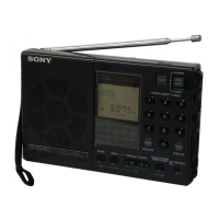
ICF-SW35
FM STEREO/SW/MW/LW
PLL SYNTHESIZED RECEIVER
Circuit system
FM: Super heterodyne
LW/MW/SW: Dual conversion super heterodyne
Frequency range
FM: 76.00 - 108.00 MHz
87.50 - 108.00 MHz*
1
SW: 2250 - 26100 kHz*
2
3850 - 26100 kHz*
3
MW: 530 - 1710 kHz
530 - 1620 kHz
LW: 150 - 285 kHz
Speaker
Approx. 66 mm (2
1/8 in.) diameter, 8 Ohms
Maximum output
240 mW (at 10 % harmonic distortion)
Output
i (headphones) jack (ø3.5 mm stereo mini jack)
16 Ohms
Power requirements
DC 4.5 V, three R6 (size AA) batteries
External power source
DC IN 4.5 V
Battery Life (approximate hours)
Sony R6 Sony LR6
(size AA) alkaline
(size AA)
FM reception 17 46
SW reception 12 33
LW/MW reception 12 33
SPECIFICATIONS
Dimensions
Approx. 168 × 106 × 35 mm (W × H × D)
(6
5/8 × 4 1/4 × 1 7/16 in.) incl. projecting parts
Mass
Approx. 405 g (14.3 oz) incl. batteries
Supplied Accessories
Carrying case (1)
Short wave guide (1)
Design and specifications are subject to change without
notice.
The AC power adaptor’s operating voltage varies
depending upon the country in which it is sold.
Buy the AC power adaptor in the country you intend
to use it.
Your Sony dealer may not handle all of the above listed
optional accessories. Please ask your dealer for detailed
information on the optional accessories available in your
country.
*
1
Italy, Saudi Arabia and Malaysia
*
2
Countries except for Italy
*
3
Italy only
Ver 1.0 2000. 03

Other manuals for Sony ICF-SW35

Question and Answer IconNeed help?

Do you have a question about the Sony ICF-SW35 and is the answer not in the manual?

Sony ICF-SW35 Specifications

General IconGeneral
Radio typePortable
Tuner typeDigital
FM band range87.5 - 108 MHz
Driver unit66 mm
Number of built-in speakers-
Display typeLED
Headphone outputs1
Product colorSilver
Battery typeAA
Battery life (max)33 h
Number of batteries supported3
Dimensions (WxDxH)168 x 35 x 106 mm
Weight and Dimensions IconWeight and Dimensions
Weight405 g

Summary

Specifications

Dimensions

Physical size of the radio unit.

Mass

Weight of the radio unit with batteries.

Supplied Accessories

Items included with the radio.

Power Requirements

Voltage and current needs for operation.

Battery Life

Estimated operational hours with different battery types.

Section 1 General

Operating the Radio

Instructions for turning on and using the radio.

Frequency Step Adjustment

Details on tuning increment adjustment.

FM Stereo Reception

How to enjoy stereo sound with headphones.

Listening Tone Settings

Adjusting tone for news or music.

MW Channel Step Setting

Changing the MW tuning step for different regions.

Tuning Functions

Scan Tuning Operation

How to automatically scan and find stations.

Attenuator Sensitivity Control

Adjusting reception sensitivity to control scan pauses.

Preset Station Management

Storing, tuning, and deleting favorite stations.

Advanced Functions

Memory Scan Tuning

Automatically scanning stations within a preset page.

Reception Improvement Techniques

Optimizing reception via antenna and external options.

Standby and Alarm Functions

Programming auto-on times and alarm features.

Sleep Timer Operation

Setting the radio to turn off automatically after a specified duration.

Control Lock and Display Light

Using the hold function to lock buttons and activating the display backlight.

Section 2 Disassembly

Cabinet Rear Disassembly

Procedure for removing the rear cabinet cover.

Main Board Disassembly

Steps to access and remove the main circuit board.

Section 2 Disassembly (continued)

Micon Board Disassembly

Procedure for removing the micon circuit board.

Section 3 Electrical Adjustments

FM Section Calibration

Calibration procedures for the FM tuning circuit.

SW/MW/LW Section Calibration

Calibration for shortwave, medium, and longwave bands.

Frequency Range and Tracking Checks

Verifying reception and tuning alignment across bands.

Section 3 Electrical Adjustments (continued)

FM VCO Adjustment Procedure

Calibrating the Voltage Controlled Oscillator for FM reception.

Section 4 Diagrams

IC Pin Description Details

Detailed pin assignments for integrated circuits.

Section 4 Diagrams (continued)

System Block Diagram Overview

Overview of the radio's internal functional blocks.

Section 4 Diagrams (continued)

Main Board Printed Wiring Layout

Visual guide to component placement on the main circuit board.

Section 4 Diagrams (continued)

Main Section Schematic Diagram

Detailed electrical wiring diagram for the main board.

Section 4 Diagrams (continued)

Micon Board Printed Wiring Layout

Visual guide to component placement on the micon circuit board.

Section 4 Diagrams (continued)

Micon Section Schematic Diagram

Detailed electrical wiring diagram for the micon board.

Section 5 Exploded View

Cabinet Section Components

Diagram showing the breakdown of the radio's cabinet parts.

Related product manuals