– 8 –
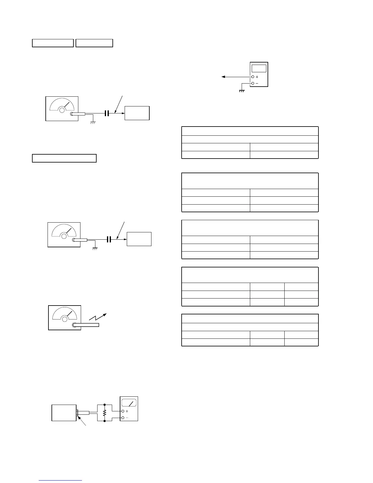
FM SECTION 0 dB = 1 µV
Setting:
BAND switch: FM
VOLUME: MAX
ATT: OFF
TONE: MUSIC
SECTION 3
ELECTRICAL ADJUSTMENTS
telescopic
antenna terminal
0.01µF
FM RF signal
generator
400Hz, 30% FM modulation
frequency deviation ±22.5kHz
Output level: as low as possible
set
SW/MW/LW SECTION
Setting:
BAND switch: SW or MW or LW
VOLUME: MAX
ATT: OFF
TONE: MUSIC
(SW)
telescopic
antenna terminal
10µF
AM RF signal
generator
400Hz, 30%
AM modulation
Output level: as low as possible
set
(MW/LW)
• Connecting Level Meter (FM, SW, MW and LW)
Put the lead-wire
antenna close to
the set.
AM RF signal
generator
400Hz, 30%
AM modulation
Output level: as low as possible
i jack (J1)
set
16 Ω
level meter
(range: 0.5–5 V ac
• Connecting Digital Voltmeter (FM, SW, MW and LW)
• Repeat the procedures in each adjustment several times, and the
frequency coverage and tracking adjustments should be finally
done by the trimmer capacitors.
AM IF ADJUSTMENT
Adjust for a maximum reading on level meter.
Frequency Display 11,800 kHz
Adjustment Part T1, T4
LW FREQUENCY COVERAGE
CHECK
Frequency Display 150 kHz
Reading on Digital voltmeter 1.0 - 1.3 V
Adjustment Part <confirmation>
SW FREQUENCY COVERAGE
CHECK
Frequency Display 26,100 kHz
Reading on Digital voltmeter 8.0 - 9.0 V
Adjustment Part <confirmation>
FM FREQUENCY COVERAGE
CHECK
Frequency Display 76 MHz 108 MHz
Reading on Digital voltmeter 2.8 - 4.0 V 9.5 - 11.0 V
Adjustment Part <confirmation> <confirmation>
FM TRACKING ADJUSTMENT
Adjust for a maximum reading on level meter.
Frequency Display 76 MHz 108 MHz
Adjustment Part L11 CT1
Adjustment Location: See page 9.