Do you have a question about the Sony ICF-SW11 and is the answer not in the manual?
Details the radio's frequency coverage across FM, SW, MW, and LW bands.
Outlines power sources, battery life, and power adapter specifications.
Specifies the approximate battery operational duration.
Provides the physical dimensions of the radio unit.
Describes the function and location of the band selection switch.
Identifies the indicator for the selected radio band.
Details the power on/off switch and its operation.
Locates and describes the telescopic antenna.
Procedure for disassembling the rear cabinet of the radio.
Steps for removing the front cabinet and main board.
Instructions for correctly setting the dial pointer.
Covers frequency coverage and tracking adjustments for the FM band.
Includes frequency coverage and tracking adjustments for MW and LW bands.
Procedure for adjusting the Intermediate Frequency (IF) for AM reception.
Adjusts the center frequency for each SW band.
Illustrates the internal block diagram of the main IC (CXA1238M-T6).
Shows the physical layout of components on the main printed wiring board.
Presents the detailed circuit schematic of the radio.
Lists and illustrates the various cabinet components and their part numbers.
Details hardware, accessories, and packing materials used in assembly.
Lists all ceramic, electrolytic, and tantalum capacitors with specifications.
Details trimmer capacitors and variable capacitors used for adjustments.
Lists the diodes used in the circuit.
Identifies the integrated circuits used in the radio.
Lists the slide switches for band and power control.
Lists transformers, specifically the AM IFT.
Lists miscellaneous components like antennas and speakers.
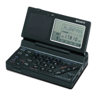
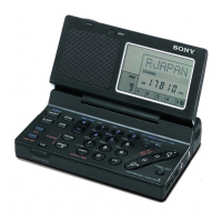
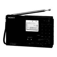
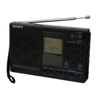
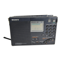
The Sony ICF-SW11 is a portable 12-band receiver designed for versatile radio reception, offering FM stereo, nine shortwave (SW1-9) bands, medium wave (MW), and long wave (LW) capabilities. This compact device is engineered for ease of use and portability, making it suitable for a wide range of listeners, from casual users to those interested in international broadcasts or amateur radio.
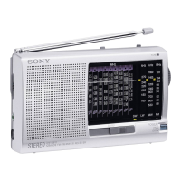
At its core, the ICF-SW11 functions as a multi-band radio receiver, capable of tuning into various radio frequencies across different bands. The FM stereo capability allows for high-fidelity audio when listening to local FM stations, especially when using headphones. The extensive shortwave coverage (SW1-9) is a key feature, enabling users to pick up broadcasts from distant regions, international news, and cultural programs, which is particularly appealing to enthusiasts of global communication. The inclusion of MW and LW bands further broadens its utility, providing access to standard AM radio broadcasts and, in some regions, specialized longwave transmissions.
The device's internal circuitry, as detailed in the block diagram, includes an IC (CXA1238M-T6) that integrates various functions such as PLL (Phase-Locked Loop) for stable tuning, an MPX (Multiplex) regulator for FM stereo decoding, and dedicated front-end circuits for FM and AM reception. This integrated design contributes to the radio's compact size and efficient performance. The presence of a decoder amplifier and ripple filter suggests an emphasis on clear audio output, minimizing interference and noise.
The ICF-SW11 is designed with user-friendly controls for intuitive operation. A prominent band select switch allows users to easily toggle between the different frequency bands (SW, LW, MW, FM). A band indicator provides visual confirmation of the currently selected band. Power is controlled by a simple ON/OFF switch.
Tuning is managed via a dedicated tuning dial, which allows for precise frequency selection. A TUNE indicator light assists users in finding the optimal signal strength for a given station. For enhanced FM reception, the radio is equipped with a telescopic antenna. When listening to shortwave, the device can also utilize a lead-wire antenna, which can be positioned for better signal acquisition.
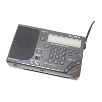
Audio output is handled by an integrated speaker, suitable for general listening. For private listening or to enjoy FM stereo in higher fidelity, a headphones jack (stereo minijack, 3.5 mm dia) is provided. The volume level is adjusted using a volume dial, offering convenient control over the audio output.
Powering the ICF-SW11 is flexible. It can operate on two R6 (size AA) batteries, providing portability and approximately 30 hours of battery life with Sony SUM-3 (NS) batteries. For extended use at home or in a fixed location, a DC IN 3V jack allows connection to an optional AC power adaptor (AC-E30L, HG), though it's noted that the AC power adaptor is not supplied with all models and voltage requirements may vary by country.
The physical design includes a stand, allowing the radio to be propped up for easier viewing and listening. The overall dimensions and mass are kept minimal, emphasizing its portable nature. A short wave guide is a supplied accessory, likely offering tips or information for optimal shortwave listening.
The service manual provides detailed instructions for disassembly and electrical adjustments, indicating that the device is designed to be serviceable by qualified technicians.
Disassembly procedures are clearly outlined, starting with the rear cabinet, then progressing to the front cabinet and main board. This systematic approach ensures that components can be accessed for repair or replacement without causing damage. Specific instructions are given for removing screws and detaching claws that secure the cabinet parts.
A critical maintenance feature is the dial pointer setting. This procedure ensures that the dial pointer accurately corresponds to the tuned frequency. It involves turning the variable capacitor fully counterclockwise, aligning a hole with a setting gap, and then adjusting the dial pointer to the center of scratched lines on the dial scale plate after turning the tuning shaft. Applying a suitable locking compound is also specified to maintain the pointer's position.
Electrical adjustments are comprehensive, covering FM frequency coverage, FM tracking, MW/LW frequency coverage, MW/LW tracking, AM IF adjustment, SW frequency center adjustment, and VCO (Voltage Controlled Oscillator) adjustment. These adjustments are crucial for maintaining the radio's performance and accuracy over time. The manual specifies the use of various test equipment, such as FM RF signal generators, AM RF signal generators, and level meters, along with specific frequencies and output levels for calibration.
The importance of adjusting the MW band first is highlighted, as LW and SW bands share components with MW, necessitating subsequent readjustments for those bands. The procedure for SW band adjustment includes setting the pointer to specific reference positions on the dial character and fixing the variable capacitor (CV1). The VCO adjustment involves connecting a frequency counter to specific points on the main board and adjusting a variable resistor (RV1) to achieve a target frequency, ensuring the stability of the tuning system.
The manual also includes a detailed electrical parts list and diagrams (IC block diagram, printed wiring board, schematic diagram), which are essential resources for troubleshooting and component replacement. These resources allow technicians to identify specific parts, understand their function within the circuit, and locate them on the physical board. The inclusion of abbreviations and notes on standardized parts helps in sourcing appropriate replacements.
Overall, the Sony ICF-SW11 is a well-designed multi-band receiver that balances user-friendliness with comprehensive serviceability, ensuring a long operational life and consistent performance across its diverse range of reception capabilities.
| Tuning System | Analog |
|---|---|
| Headphone Jack | Yes |
| Antenna | Telescopic Antenna |
| Frequency Range (AM) | 530 - 1710 kHz |
| Speaker | Built-in |
| Type | Portable Radio Receiver |
| Power Source | 2 x AA batteries or AC adapter |