ILCE-7SM2_L2
2-8
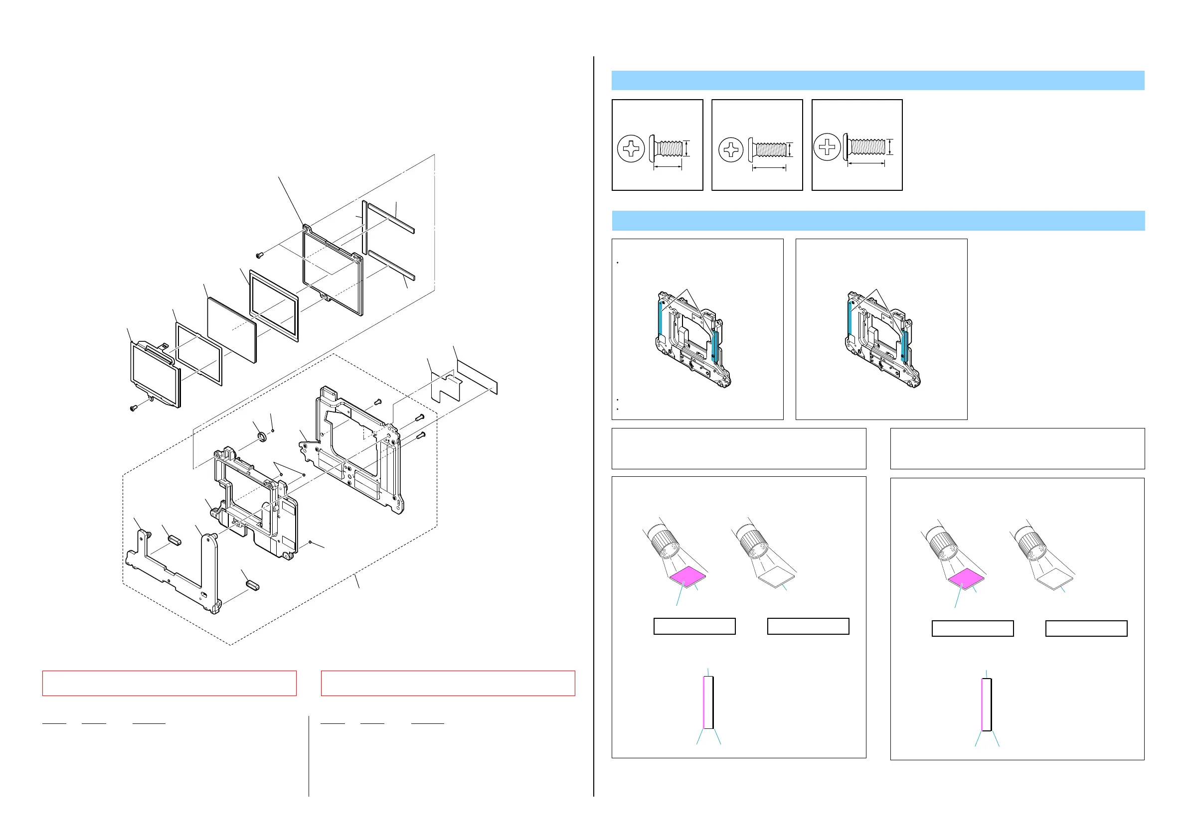
2-1-6. IMAGER UNIT SECTION
ns: not supplied
Ref. No. Part No. Description
251 1-493-074-21 OPTICALFILTERBLOCK (OFB-01-134) (Note 3)
252 4-536-532-01 IM SHEET(3200), SPACE (Note 2)
253 4-575-430-01 IM MASK PLATE (5100)
254 4-575-771-01 SHEET (A (795)), RADIATION (GF)
255 4-575-946-01 IM GRAPHITE SHEET (5100)
Screw
#191: M1.7 X 3.5
(Black)
4-188-735-01
3.5
1.7
5.0
1.7
#267: M1.7 X 5.0
(Red)
4-287-436-21
#328: M1.7 X 4.0
(Black)
3-091-481-31
4.0
1.7
256 (Note 1)
#328
(Note 4)
#191
#267
#267
#328
(Note 4)
ns
ns
ns
ns
ns
ns
ns
251
(Note 3)
ns
ns
253
257
258
258
258
252
(Note 2)
(All mounted parts and IS-1030 complete board are not supplied,
but they are included in Device Service (5200).)
255
254
ns
ns
Note
Note 1: Note 1:
ここを 持ってください。
Don’t bring iron-based material close to Unit.
Don’t apply power to Flexible cable.
Hold the MB N Contact Unit at the center of
both sides.
・鉄系金属物を近づけないこと。
・フレキシブルケーブルには力をかけないこと。
・MBNContactUnitの両側の中央部を持つ
こと。
Hold here.
Note 2: When attaching the SPACE IM SHEET (3200) to the imager
to the OPTICAL FILTER BLOCK (OFB-01-134), attach them
so that the each centers are matched and top and bottom
right and left become uniform.
Note 2:
SPACEIMSHEET(3200)をイメージャと光学フィルタブロッ
ク(OFB-01-134)に取りつける時は,上下左右が均一になる
ようにそれぞれの中心を合わせて取り付けてください。
Note 3: Confirm the mounting direction of the optical filter block by
shedding light from obliquely when attaching the OPTICAL
FILTER BLOCK to the imager.
Optical Filter Block (OFB-01-134) mounting direction
Optical Filter
Block (OFB-01-134)
Reflected in red
UV/IR coated surface
UV/IR coated surface AR coated surface
AR coated surface
Optical Filter Block (OFB-01-134)
Optical Filter
Block (OFB-01-134)
Imager sideMount side
Note 3:
光学フィルタブロックをイメージャに取り付ける時は,光
学フィルタブロックに光を斜めから投じて,取り付ける向
きを確認してください。
光学フィルタブロック(OFB-01-134)取り付け向き
光学フィルタブロック
(OFB-01-134)
赤に反射
UV/IRコーティング面
UV/IRコーティング面 ARコーティング面
ARコーティング面
光学フィルタブロック(OFB-01-134)
光学フィルタブロック
(OFB-01-134)
イメージャ側マウント側
Note 4: This screw cannot be reused. Discard the screw removed
once in servicing. Instead, use a new screw.
Note 4:
このねじは再利用することができません。サービス対応時
に一度でも外した場合は新品のねじと交換してください。
256 A-2057-628-B TEX-7860 (Note 1)
257 4-558-096-01 AS RING CUSHION B
258 4-558-102-01 AS BALL
#191 4-188-735-01 SCREW (M1.7)
#267 4-287-436-21 SCREW (M1.7)
#328 3-091-481-31 SCREW (Note 4)
Ref. No. Part No. Description
 Loading...