ILCE-7SM2_L2
2-7
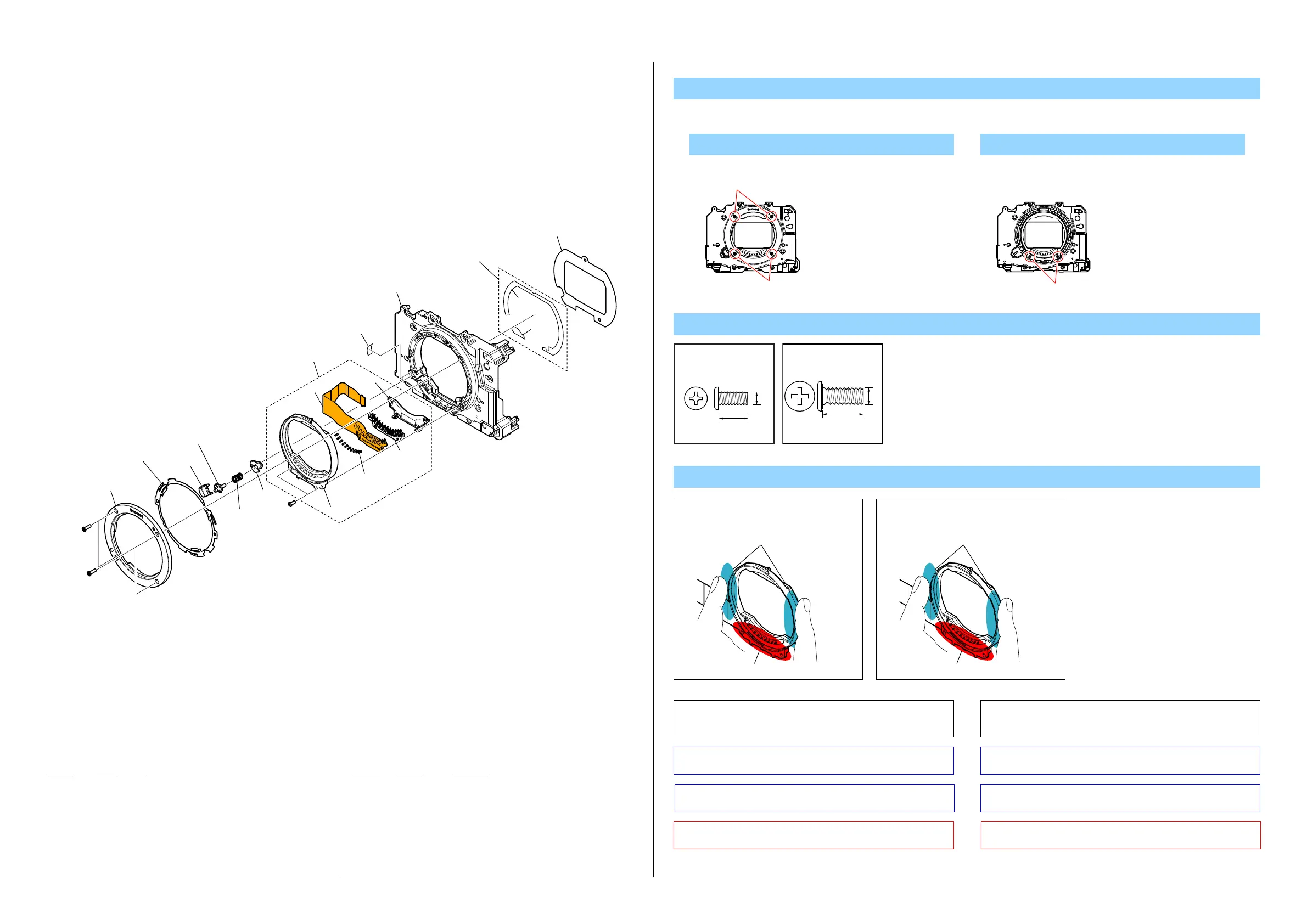
2-1-5. MB N FRAME SECTION
ns: not supplied
Ref. No. Part No. Description Ref. No. Part No. Description
Note
201 4-558-370-11 MB N PLATE A (5000)
* 202 4-185-963-01 MB N PLATE SP (Note 3)
203 X-2590-636-1 MB L LOCK PIN ASSY (5000)
* 204 4-186-538-01 SPRING, LENS LOCK
205 4-484-357-01 HOLDER, LENS LOCK (3000)
206 4-564-120-01 BUTTON (786), LENS LOCK
207 A-2080-154-A MB N CONTACT UNIT (3000) (Note 1)
208 4-558-372-01 MB MASK SHEET TAPE (5000) (Note 4)
209 4-558-371-01 MB MASK SHEET (5000)
210 4-443-530-01 MB N PIN (H) (Note 2)
211 4-424-667-01 MB SP (755), N (Note 2)
212 4-576-772-01 MB SHIELD SHEET L LOCK (5100)
#234 4-186-545-11 SCREW, 0+Z M1.7 SG (SPIN) (Note 5)
#328 3-091-481-31 SCREW (Note 5)
DISASSEMBLY
1. Remove in numerical order (1 to 7) in the left figure.
1 #234 X 4 6 #328 X 2
Note 2: These parts are able to replace from the state of the
finished product. Refer to the section “1-4. MB N SP (755)
and MB N PIN (H) REPLACING METHOD”.
Note 2:
これらの部品は完成した状態から交換することが可能です。
「1-4. MB N バネ (755),MB N ピン Hの交換方法」を参照し
てください。
Screw
#234
ns
ns
(Note 2)
(Note 2)
(Note 3)
(Note 1)
(Note 4)
ns
#234
#328
ns
ns
ns
201
202
206
207
208
209
203
212
204
205
210
211
1
2
3
6
7
4
5
(Note 5)
(Note 5)
(Note 5)
#234
Front View
#234
Front View
#328
#234: M1.7 X 5.5
(Silver)
4-186-545-11
5.5
1.7
#328: M1.7 X 4.0
(Black)
3-091-481-31
4.0
1.7
Note 1:
Hold the MB N Contact Unit at
the center of both sides.
Hold here.
Don't touch this part.
Note 1:
MB N Contact Unitの両側の
中央部を持ってください。
ここを 持ってください。
この部分に触れないでください。
Note 3: Refer to “Assembly-3: Apply grease on the MB N Plate SP”
on page 3-1.
Note 3:
3-1ページの“Assembly-3:ApplygreaseontheMBNPlate
SP”を参照してください。
Note 4: Refer to “Assembly-2: Method of attachment of the MB
Mask Sheet (5000)” on page 3-1.
Note 4:
3-1ページの“Assembly-2:MethodofattachmentoftheMB
MaskSheet(5000)”を参照してください。
Note 5: This screw cannot be reused. Discard the screw removed
once in servicing. Instead, use a new screw.
Note 5:
このねじは再利用することができません。サービス対応時
に一度でも外した場合は新品のねじと交換してください。
 Loading...