ILCE-7SM2_L2
2-6
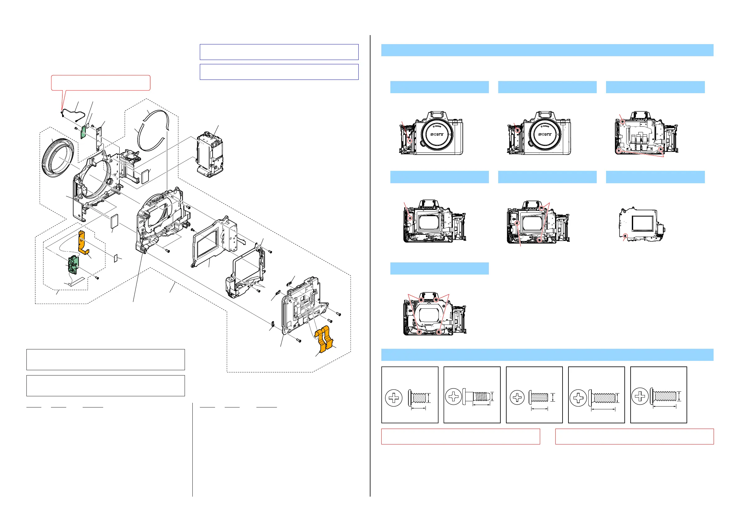
2-1-4. MECHA DEVICE SECTION
ns: not supplied
DISASSEMBLY
1. Remove in numerical order (1 to 7) in the left figure.
Ref. No. Part No. Description
Ref. No. Part No. Description
151 4-188-536-01 CAP, BODY
152 1-846-474-21 CABLE, COAXIAL (85MM)
153 A-2083-075-A AN-1019 BOARD, COMPLETE
154 4-564-218-01 SHEET (786), IR
155 4-559-165-01 PLATE, WIFI
156 A-2091-638-A COVER BLOCK ASSY (SERVICE)
157 4-575-778-01 SHEET (795), N
158 A-2068-791-A FLEXIBLE BLOCK ASSY (SERVICE)
159 A-2071-013-A JK-1012 BOARD, COMPLETE (SERVICE)
160 1-493-061-11 SHUTTER UNIT (AFE-3379)
161 A-2083-735-A MB CHARGE UNIT (5100)
162 1-893-810-11 ISP-2003 FLEXIBLE BOARD
163 1-894-513-11 ISL-2004 FLEXIBLE BOARD
164 1-893-807-11 FP-2280 FLEXIBLE BOARD
165 A-2085-439-A SERVICE, MECHA DEVICE (5200)
166 4-559-473-01 SHEET (A), DROP PROTECTION
167 4-564-093-01 SHEET, JK BLIND
168 4-577-710-01 SHEET (B), JK BLIND
#1 2-635-562-11 SCREW (M1.7)
#197 4-185-990-01 MB SCREW, CHARGE UNIT FIXED
#233 2-342-356-11 SCREW (M2 (ECO, EG)) (Note 3)
#273 2-342-356-21 SCREW (M2 (ECO, EG)) (Note 3)
#328 3-091-481-31 SCREW (Note 3)
Screw
#1: M1.7 X 2.5
(Black)
2-635-562-11
2.5
1.7
#197: M1.6 X 4.5 (Tapping)
(Silver)
4-185-990-01
4.5
1.6
#233: M2.0 X 5.0
(Black)
2-342-356-11
5.0
2.0
#273: M2.0 X 6.0
(Black)
2-342-356-21
6.0
2.0
#233
(Note 1)
(Note 2)
(Note 1)
(Note 1)
#273
#328
#328
#273
ns
ns
ns
ns
#273
#233
(including BT901 (battery terminal) and
BT-2008 flexible board)
#197
#328
#1
#1
157
158
151
152
153
154
155
156
166
166
159
167
165
164
157
160
161
162
163
168
1
2
3
4
6
5
7
MB N Frame Section
(See page 2-7)
Imager Unit Section
(See page 2-8)
When removing and re-assembling,
pull this connector vertically from the board.
(Note 3)
(Note 3)
(Note 3)
(Note 3)
(Note 3)
(Note 3)
(Note 3)
(Note 3)
#1
Front View
Front View
#1
Back View
#273
#273
1 #1 X 1 2 #1 X 1 3 #273 X 3
Back View
#328
Back View
#328
#328
Front View
#197
4 #328 X 1 5 #328 X 3 6 #197 X 1
Back View
#233
#233
7 #233 X 4
Note 1: The IM adjust washers differ in thickness.
Make sure to return the removed IM adjust washers to
original places. Do not lose them.
Note 1:
IM調整ワッシャは,それぞれ厚さが異なります。
取り外したIM調整ワッシャは,必ず元の位置に戻してください。
また,紛失に注意してください。
#328: M1.7 X 4.0
(Black)
3-091-481-31
4.0
1.7
Note 2: Refer to “Assembly-1: Screw tightening sequence when
assembling the Imager Unit” on page 3-1.
Note 2:
3-1ページの“Assembly-1:Screwtighteningsequencewhen
assemblingtheImagerUnit”を参照してください。
Note 3: This screw cannot be reused. Discard the screw removed
once in servicing. Instead, use a new screw.
Note 3:
このねじは再利用することができません。サービス対応時
に一度でも外した場合は新品のねじと交換してください。
 Loading...