Do you have a question about the Sony ILME-FX6V and is the answer not in the manual?
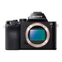
Compares features across different ILME-FX6 models.
Illustrates the physical placement of internal circuit boards within the camcorder.
Explains the function and components of various circuit blocks within the camcorder.
Lists and describes the various connectors and cables used in the camcorder.
Details the input and output signals for each camcorder connector.
Explains the meaning and normal state of onboard LED indicators on specific boards.
Provides crucial instructions and precautions for replacing specific internal components and boards.
Lists specialized tools and fixtures required for service and repair procedures.
Details circuit protection components like thermistors and fuses, including their specifications.
Outlines the process and requirements for performing electrical adjustments on the unit.
Provides guidance on the proper handling and connection/disconnection of internal cables.
Describes the procedure for cleaning critical optical components to maintain image quality.
Covers fundamental principles for part replacement, including tightening torque and board markings.
Details the procedure for removing and installing the main external covers of the camcorder.
Explains how to access and remove internal panels to reach various components.
Outlines the steps for removing and replacing external panels on the camcorder body.
Provides specific instructions for the replacement of the VC-1046 main processing board.
Describes the procedure for removing and replacing the front section of the camcorder.
Details the disassembly and reassembly of the camcorder's detachable handle unit.
Explains the steps for disassembling and reassembling the camcorder's grip assembly.
Lists error codes displayed on the viewfinder and their corresponding check and action procedures.
Introduces the Service menu and its purpose for maintenance and adjustment.
Explains the steps required to access and display the camcorder's Service menu.
Explains how to acquire and manage operation logs and AllFile files for diagnostics.
Provides important notes regarding the use, standardization, stock, and registration of repair parts.
Presents detailed exploded diagrams of the camcorder's components for identification.
Shows overall block diagrams illustrating the interconnectedness of major camcorder components.