Do you have a question about the Sony KDL-65W5100 and is the answer not in the manual?
Procedure for removing the rear cover of the TV set.
Steps to remove the switch unit from the front cabinet assembly.
Instructions for removing the BU, BH2, and G8 (Power) boards.
Steps to remove the table-top stand and under cover.
Guide for safely removing the loudspeakers and tweeters.
Removal procedures for structural parts and AC inlet.
Detailed steps for removing the LCD panel and associated modules.
Important precautions and methods for cleaning the LCD panel safely.
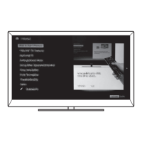
Information on how to view service adjustment data on the TV.
Procedure to enter the service adjustment mode using the remote.
Using the remote commander to navigate and view service data.
Guide to setting the correct destination after replacing the BU board.
Instructions to restore user controls and channel memory to factory settings.
Diagram showing the physical location of main circuit boards within the TV.
Explains symbols and conventions used in schematic diagrams.
Overview of the TV's main functional blocks and their interconnections.
Illustrates the path of video and audio signals through the system.
Provides detailed schematics for specific boards (e.g., BH2).
Exploded view of the rear cover and table-top stand assembly.
Exploded view of the TV chassis and major internal components.
Diagram showing all external and internal connectors and their assignments.
Exploded view detailing the bezel, LCD panel, and related parts.
A guide to identify screws used in the assembly and their quantities.
List of electrical components for the BH2 board.
List of electrical components for the BU board.
| Screen Size | 65 inches |
|---|---|
| Resolution | 1920 x 1080 |
| Display Type | LCD |
| Backlight Type | CCFL |
| Refresh Rate | 60Hz |
| HDMI Ports | 4 |
| USB Ports | 2 |
| Smart TV | No |
| Built-in Wi-Fi | No |
| 3D Capable | No |
| Weight | 25.4 kg |