Do you have a question about the Sony KLV-V40A10E and is the answer not in the manual?
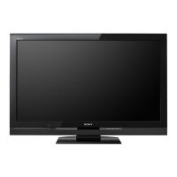
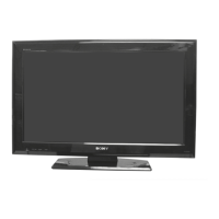
| Screen Size | 40 inches |
|---|---|
| Display Resolution | 1366 x 768 pixels |
| Display Type | LCD |
| HD Type | HD Ready |
| Aspect Ratio | 16:9 |
| Brightness | 500 cd/m² |
| Contrast Ratio | 1300:1 |
| Viewing Angle | 178° |
| Response Time | 8 ms |
| HDMI Ports | 1 |
| USB Ports | 0 |
| Smart TV | No |
| Inputs | Composite, Component |
| Sound Output | 20 W |
Lists LED error codes and their corresponding error descriptions for chassis diagnostics.
Step-by-step instructions for removing the rear cover of the TV for internal access.
Instructions for safely removing the TV stand assembly from the unit.
Procedure for removing internal mounting brackets within the TV chassis.
Steps for disconnecting and removing the left and right loudspeakers.
Instructions on how to remove the internal cooling fan unit from the TV.
Procedure for removing the A2 main board from the TV chassis.
Steps for removing the BL, N, and NP1 boards, noting specific models for N board.
Instructions for removing the G3L board, typically associated with power supply functions.
Procedure for removing the H7 board, which often contains LED indicators.
Steps for removing the H8 board, often related to side signal inputs.
Instructions for removing the H6 board, typically related to control buttons.
Detailed steps and diagrams for placing the TV in a service position for component access.
Guides on accessing the service mode using the remote commander and menu system.
Detailed procedures for calibrating signal levels (Y, C, CR) for various video inputs.
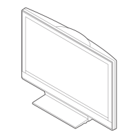
Exploded view of the TV chassis assembly showing major mechanical parts.
Exploded view detailing the display unit assembly and its components.