Do you have a question about the Sony KV-1946R and is the answer not in the manual?
Procedures for adjusting Video IF stages using sweep and marker signals.
Steps to align the Sound IF section for optimal audio output.
Procedure for testing electrical leakage to ensure user safety.
Method for identifying a reliable earth ground connection for testing.
Alignment steps for the Chroma Bandpass circuit.
Procedure for aligning the 3.58MHz trap circuit.
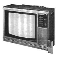
Instructions for removing the cabinet and the Cathode Ray Tube.
Common symptoms and likely component failures for picture, sound, and sync problems.
Procedures for channel pre-tuning and adjusting picture settings.
Adjustments for horizontal and vertical picture parameters.
Procedures for aligning color, tint, and purity for accurate display.
Specific adjustment for the failsafe circuit when replacing components.
Diagrams showing component placement and the electrical schematic for the remote.
Resistance measurements for IC pins and transistor terminals for troubleshooting.
Lists of capacitors and coils with their specifications and replacement data.
Lists of transistors and diodes with their types and replacement data.
Lists of ICs and switches with their functions and part numbers.
Cross-reference data for semiconductor replacements, including various manufacturer part numbers.
Detailed lists of electrolytic and other capacitor types with ratings and part numbers.
Lists of resistors, controls, and RF-IF coils with their specifications.
Lists of miscellaneous components and cabinet parts with their descriptions.
Information on wiring specifications, including wire types and cable recommendations.
Lists of transformers, speaker, and fuse devices with their specifications.
| Screen Size | 19 inches |
|---|---|
| Display Technology | CRT |
| Color System | NTSC |
| Inputs | RF |
| Resolution | Not specified in available documentation |