EasyManua.ls Logo

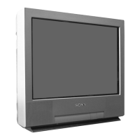
Sony KV-21FM100 User Manual

Sony KV-21FM100
95 pages
To Next Page IconTo Next Page
Page #1 background imageLoading...
Page #1 background image
TRINITRON
®
COLOR TELEVISION
SERVICE MANUAL
BA-6
CHASSIS
MODEL NAME REMOTE COMMANDER DESTINATION CHASSIS NO.
9-965-922-02
KV-20FS100
RM-Y173 US SCC-S61A-A
KV-20FS100
RM-Y173 CND SCC-S59A-A
KV-20FV300
RM-Y180 US SCC-S61B-A
KV-20FV300
RM-Y180 CND SCC-S59B-A
KV-21FM100
RM-Y172 LATIN NORTH SCC-S60E-A
KV-21FM100
RM-Y172 LATIN SOUTH SCC-S60F-A
KV-21FS100
RM-Y173 LATIN NORTH SCC-S60A-A
KV-21FS100
RM-Y173 LATIN SOUTH SCC-S60B-A
KV-21FV300
RM-Y180 LATIN SOUTH SCC-S60D-A
KV-21FV300
RM-Y180 LATIN NORTH SCC-S60C-A
KV-24FV300
RM-Y180 US SCC-S61C-A
KV-24FV300
RM-Y180 CND SCC-S59C-A
KV-25FV300
RM-Y180 LATIN NORTH SCC-S60G-A
KV-25FV300
RM-Y180 LATIN SOUTH SCC-S60H-A
HISTORY INFORMATION FOR THE FOLLOWING MANUAL:
ORIGINAL MANUAL ISSUE DATE: 2/2002
ALL REVISIONS AND UPDATES TO THE ORIGINAL MANUAL ARE APPENDED TO THE END OF THE PDF FILE.
REVISION DATE REVISION TYPE SUBJECT
2/2002 No revisions or updates are applicable at this time.
2/2002 Supplement - 1 New A Board Schem. and PWB, New CV Board Schem., New M3 Board Schem.,
R039, R565, R1761 P/N Correction.

Table of Contents

Question and Answer IconNeed help?

Do you have a question about the Sony KV-21FM100 and is the answer not in the manual?

Sony KV-21FM100 Specifications

General IconGeneral
Screen Size21 inches
Display TypeCRT
Aspect Ratio4:3
TunerAnalog
SpeakersBuilt-in
InputsComposite

Summary

Disassembly

Rear Cover Removal

Procedure for removing the rear cover of the TV unit.

Chassis Assembly Removal

Procedure for removing the main chassis assembly from the unit.

Service Position

Correct positioning of the chassis for service access.

Picture Tube Removal

Steps for safely removing the picture tube from the chassis.

Set-Up Adjustments

Beam Landing

Adjusting electron beam alignment for optimal picture.

Convergence

Aligning red, green, and blue dots for sharp image clarity.

Focus

Adjusting the focus control for best picture sharpness.

Screen (G2)

Adjusting screen grid voltage for picture brightness and contrast.

Method of Setting the Service Adjustment Mode.

Procedure to enter and navigate the service adjustment mode.

White Balance Adjustments

Calibrating color reproduction for accurate white balance settings.

Safety Related Adjustments

R565 Confirmation Method (HV Hold-Down Confirmation) and Readjustments

Verifying high voltage stability and performing related readjustments.

B+ Voltage Confirmation and Adjustment

Checking and adjusting the B+ voltage supply for proper operation.

Circuit Adjustments

Setting the Service Adjustment Mode.

Steps to access and configure the service adjustment mode.

Remote Adjustment Buttons and Indicators

Overview of remote control buttons and indicators used for adjustments.

ID Map Table

Table detailing ID settings for different model and destination combinations.

A Board Adjustments

Specific adjustment procedures for the A Board components.

Diagrams

Circuit Boards Location

Identification and location of major circuit boards within the TV.

Block Diagram and Schematics

High-level block diagram and detailed circuit schematics.

Semiconductors

Identification and diagrams of common semiconductor components.

Exploded Views

Chassis (KV-21FM100 ONLY)

Exploded view of chassis parts specific to the KV-21FM100 model.

Chassis (KV-20FS100/21FS100 ONLY)

Exploded view of chassis parts for KV-20FS100 and KV-21FS100 models.

Chassis (KV-20FV300/21FV300 ONLY)

Exploded view of chassis parts for KV-20FV300 and KV-21FV300 models.

Chassis (KV-24FV300/25FV300 ONLY)

Exploded view of chassis parts for KV-24FV300 and KV-25FV300 models.

Electrical Parts List

A Board Common Parts List

List of common parts used on the A Board across multiple models.

Related product manuals