Do you have a question about the Sony Trinitron KV-21FT250 and is the answer not in the manual?
Key technical details about the TV, including power, dimensions, and inputs.
Lists registered trademarks associated with Sony products.
Highlights critical components essential for safe operation and proper replacement.
Ensures proper repair execution, including connection checks and AC leakage testing.
Explains STANDBY LED flash codes for identifying error sources and symptoms.
Guides on accessing, interpreting, and clearing diagnostic results for troubleshooting.
Step-by-step instructions for accessing internal components by removing the rear cover and speakers.
Procedures for safely removing the main chassis assembly and the CRT picture tube.
Detailed instructions and warnings for safely discharging and removing the picture tube anode cap.
Specific guidance on connecting and dressing wires on the H3 board and associated connectors.
Instructions for routing wires on the A and C boards, ensuring proper placement and preventing damage.
Procedures for dressing AC power cords and speaker wires, focusing on heat and physical protection.
Covers dressing procedures for DY, FBT, HV Cap, and AC power cords for optimal internal layout.
Steps for aligning electron beams and color convergence on the screen for picture clarity.
Procedures for fine-tuning picture focus and screen brightness levels.
Identifies remote buttons for service access and lists required test equipment.
Detailed guide on entering the service menu and navigating through adjustment categories.
Steps for adjusting white balance, color temperature, and other picture quality parameters.
Adjustments for screen geometry and settings specific to PAL/NTSC color systems.
Shows locations of main boards and explains schematic symbols and notations.
Provides a high-level overview of the TV's signal flow and functional blocks.
Contains schematics for specific boards (A, C, H3) and associated waveform references.
Lists common semiconductor devices with package types for easy identification.
Illustrates the mechanical structure of the TV for component replacement and identification.
Detailed list of capacitors and resistors with part numbers, values, and specifications.
Comprehensive list of diodes, integrated circuits, connectors, and other electronic parts with part numbers.
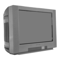
| Screen Size | 21 inches |
|---|---|
| Display Technology | CRT |
| Aspect Ratio | 4:3 |
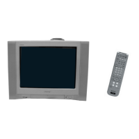
| Remote Control | Included |
| Input Ports | Composite, RF |
| Tuner | Analog |
| Power Consumption | 90W |
| Weight | 24 kg |
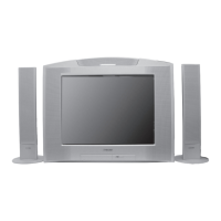
| Audio Output | 2 x 5W speakers |