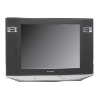
KV-21FT250
KV-21FT250
3
TABLE OF CONTENTS
Specifi cations ................................................................................. 4
Warnings and Cautions .................................................................. 5
Safety Check-Out ........................................................................... 6
Self-Diagnostic Function ................................................................. 7
SECTION 1: DISASSEMBLY ................................................................. 9
1-1. Rear Cover Removal .............................................................. 9
1-2. Speaker and Tweeter Removal .............................................. 9
1-3. Chassis Assembly Removal ................................................. 10
1-4. Service Position ................................................................... 10
1-5. Picture Tube Removal ...........................................................11
Anode Cap Removal Procedure ...........................................11
SECTION 2: WIRE DRESSING ........................................................... 12
2-1. H3 Board Caution Point ....................................................... 12
2-2. A Board UL Wire Dressing ................................................... 12
2-3. Connector Assembly Caution ............................................... 12
2-4. C Board ................................................................................ 13
2-5. A Board ................................................................................ 13
2-6. A Board (Continued) ............................................................. 14
2-7. AC Power Cord and Speakers ............................................. 15
2-8. AC Power Cord and Speakers (Continued) ...................... 16
2-9. DY Wire Dressing ................................................................. 17
2-10. FBT Wire Dressing ............................................................... 18
2-11. HV Cap Assembly ................................................................ 19
2-12. AC Power Cord to Rear Cover ............................................. 19
SECTION 3: SET-UP ADJUSTMENTS ................................................ 20
3-1. Beam Landing Adjustment ................................................... 20
3-2. Convergence Adjustment ..................................................... 21
3-3. Focus Adjustment ................................................................. 22
3-4. G2 (Screen) Adjustment ....................................................... 23
SECTION 4: CIRCUIT ADJUSTMENTS .............................................. 24
4-1. Remote Adjustment Buttons and Indicators ......................... 24
4-2. Accessing the Service Menu Mode ...................................... 25
4-3. Confi rming Service Adjustment Changes ............................. 26
4-4. White Balance Adjustments ................................................. 26
4-5. Picture Quality Adjustments ................................................. 26
4-6. Service Data ......................................................................... 28
SECTION 5: DIAGRAMS ..................................................................... 43
5-1. Circuit Boards Location ........................................................ 43
5-2. Printed Wiring Board and Schematic Diagram Information .. 43
5-3. Block Diagram ...................................................................... 44
5-4. Schematics and Supporting Information .............................. 45
A Board Schematic Diagram (1 of 6) .................................... 45
A Board Schematic Diagram (2 of 6) .................................... 46
A Board Schematic Diagram (3 of 6) .................................... 47
A Board Schematic Diagram (4 of 6) .................................... 48
A Board Schematic Diagram (5 of 6) .................................... 49
A Board Schematic Diagram (6 of 6) .................................... 50
C Board Schematic Diagram ................................................ 52
H3 Board Schematic Diagram .............................................. 53
5-5. Semiconductors ................................................................... 54
SECTION 6: EXPLODED VIEWS ........................................................ 55
6-1. Chassis, Picture Tube and Speakers ................................... 55
SECTION 7: ELECTRICAL PARTS LIST ............................................ 56
SECTION TITLE PAGE SECTION TITLE PAGE




 To Next Page