TRINITRON
®
COLOR TELEVISION
SERVICE MANUAL
BX-1S
CHASSIS
MODEL NAME REMOTE COMMANDER DESTINATION CHASSIS NO.
9-965-997-01
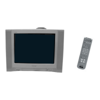
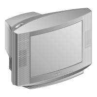
KV-21FS140
RM-YA005 LATIN NORTH SCC-S79A-A
KV-21FS140
RM-YA005 LATIN SOUTH SCC-S79B-A
HISTORY INFORMATION FOR THE FOLLOWING MANUAL:
ORIGINAL MANUAL ISSUE DATE: 2/2006
REVISION DATE SUBJECT
2/2006 No revisions or updates are applicable at this time.