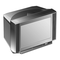
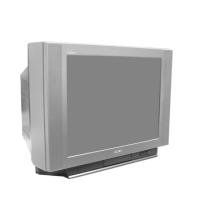
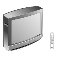
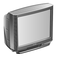
Do you have a question about the Sony KV-25FV300 and is the answer not in the manual?
Key safety warnings for electrical shock and component handling.
Essential checks after service for customer safety.
LED flash codes, screen display, handling, and clearing diagnostic results.
Diagram and explanation of the self-diagnostic circuit and error detection.
Instructions for removing the rear cover and chassis assembly.
Detailed steps for removing the picture tube and anode cap.
Procedure for adjusting beam landing using purity control and disk magnets.
Adjusting vertical, horizontal convergence, size, linearity, and trapezoid.
Adjusting focus, screen (G2), white balance, and color settings.
Procedures for entering service mode and managing adjustments.
Procedure for confirming and readjusting R565 for HV hold-down.
Procedure for confirming and adjusting B+ voltage.
Entering service mode, confirming memory writes, and remote control functions.
Lists of adjustable parameters for various devices (DEF, 16:9, VP1).
Detailed procedures for picture adjustments like display position, brightness, and color.
Checking H/V frequencies and adjusting SCON waveform levels.
Adjusting display characters to the center of the screen.
Adjusting SBRT, SHUE, and SCOL for picture quality.
Adjusting picture geometry, linearity, and shape parameters.
Adjusting vertical angle, bow, and pin settings for picture shape.
Diagrams showing board locations and notes on schematic symbols.
High-level functional block diagram of the TV system.
Schematics, locator table, waveforms, voltage lists, and IC block diagrams for the A Board.
Schematic diagrams for CV, HR, and M3 boards.
Exploded view and parts list for the KV-21FM100 chassis.
Exploded view and parts list for KV-20FS100/21FS100 chassis.
Exploded view and parts list for KV-20FV300/21FV300 chassis.
Exploded view and parts list for KV-24FV300/25FV300 chassis.
Common and variant parts lists for the A Board.
Lists of capacitors, diodes, and integrated circuits.
Lists of jacks, coils, transistors, resistors, and varistors.
Lists for connectors, fuses, transformers, tuners, and other components.
Detailed parts list for the CV board.
Part details for the HR Board, including components and connectors.
Part details for the M3 Board, including components and resistors.
List of part numbers for accessories like antennas, cables, and batteries.
Information on included manuals and packing contents.
Details new schematics and corrected part numbers for A, CV, and M3 boards.
Guidance on incorporating the supplement into the service manual.
Correction for R039 part number from incorrect to correct value.
Correction for R565 part number from incorrect to correct value.
Correction for R1781 part number from incorrect to correct value.
Instructions for printing non-schematic pages, schematics, and specific sections.
How to use the search function to locate components and text within the manual.
| Screen Size | 25 inches |
|---|---|
| Display Technology | CRT |
| Aspect Ratio | 4:3 |
| Resolution | 480i |
| Inputs | Composite, S-Video |
| Tuner | Analog |






 Loading...