Do you have a question about the Sony Trinitron KV-25FX20A and is the answer not in the manual?
Explains basic operations using the remote control for TV functions.
Guides on channel tuning and adjusting picture parameters for optimal display.
Details how to adjust audio settings and set the automatic TV power-off timer.
Covers teletext, external connections, common problems, and technical specs.
Steps for removing the rear cover, chassis, and placing the unit in service position.
Procedures for removing specific internal circuit boards like H and S1 boards.
Detailed steps for removing the picture tube and safely handling the anode cap.
Instructions for removing and refitting bottom plates on the main chassis bracket for service access.
Procedure to adjust beam landing and purity for correct color convergence.
Steps for adjusting static and dynamic convergence for accurate RGB color alignment.
Adjusting focus for sharp images and white balance for accurate color reproduction.
Guide on accessing service mode and performing electrical adjustments using the remote.
Details the various functions and tests available within Test Mode 2.
High-level system diagrams illustrating the overall TV circuitry.
Identifies the physical location of key circuit boards within the TV chassis.
Detailed circuit schematics and printed wiring board layouts for service reference.
Illustrated breakdown of the TV chassis showing major assemblies and parts.
Detailed illustration of the picture tube assembly and its components.
Comprehensive lists of parts for various circuit boards (F, A, C, VM, H, K, S1) used in the TV.
Lists included accessories, packaging materials, and related manuals.
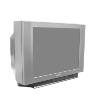
| Screen Size | 25 inches |
|---|---|
| Display Technology | CRT |
| Screen Type | Flat |
| Aspect Ratio | 4:3 |
| Audio Output | Stereo |
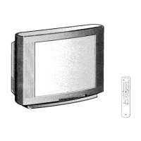
| Remote Control | Yes |
| Audio Output Power | 10W (5W x 2) |
| Inputs | Composite, RF |