EasyManua.ls Logo

Sony Trinitron KV-25XBR User Manual

Sony Trinitron KV-25XBR
126 pages
To Next Page IconTo Next Page
Page #1 background imageLoading...
Page #1 background image
1¢.
1
-- --------- ---
SERVICE MANUAL
US Model
Chassis No. SCC-595B-A
December, 1984
P2BcHAss1s
Television system
SPEC! Fl CATIONS
Outputs
TV OUT (AV jack)
American TV standards
Channel coverage
Picture tube
Antenna
Inputs
'I/IICROFILM
VHF: 2-13
UHF: 14-69
Cable TV: 1-125
Microblack Trinitron
25-inch picture measured
diagonally
114-degree deflection
75-ohm external antenna terminal
for VHF/UHF/CATV
VIDEO 1, 3 INPUT (phono jacks)
Video: 1 V p-p, 75 ohms
unbalanced, sync negative
Audio: 408mVrms (100% modula-
tion, 47 kilohms)
VIDEO 2 IN AV (AV jack)
Video: 1 Vp-p, 75 ohms unbalanc-
ed, sync negative
Audio: 408mVrms (100% modula-
tion, 47 kilohms)
RGB MULTI INPUT (See next page.)
CONTROL IN (minijack)
5V p-p
75-ohm external antenna terminal
for VHF/UHF/CATV
AUX 75-ohm auxiliary antenna
terminal
FROM TV STAND connector tor the
optional SU-171 TY stand
Video: 1 Vp-p, 75 ohms unbalanc-
ed, sync negative
Audio: 408mVrms (100%
modulation, 5 kilohms)
MONITOR OUTPUT (phono jack)
Video: 1 Vp-p, 75 ohms
unbalanced, sync negative
Audio: 408mVrms (100%
modulation, 5 kilohms)
CONTROL OUT (minijack)
5V p-p
PHONES (stereo minijack)
Accepts 8-ohm headphones
SPEAKER
Accepts speakers of 8 ohms
TO CONVERTER terminal
Power requirements
120V AC, 60 Hz
Power consumption
185 W (max.)
1.5 W (in standby condition)
Dimensions 635 x 547 x 478 mm (25 x 215/s x
187/s inches) without speakers
700 x 547 x 478 mm (275/s x 215/s
x 187/s inches) including speakers
Weight 45 kg (991b 4oz)
(without speakers)
- Continued on page 2 -
TRINITRON® COLOR TV
SONY:
Question and Answer IconNeed help?

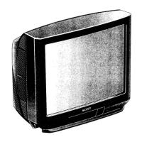
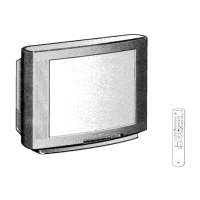
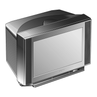
Do you have a question about the Sony Trinitron KV-25XBR and is the answer not in the manual?

Sony Trinitron KV-25XBR Specifications

General IconGeneral
Screen Size25 inches
Display TechnologyCRT
Aspect Ratio4:3
Video InterfaceComposite, S-Video
Audio OutputsStereo RCA
SpeakersStereo

Summary

SAFETY-RELATED COMPONENT WARNING

Confirming of Hold Down Circuit

Checks for HV hold down circuit operation and voltage confirmations.

PROTECTOR CONFIRMATION

Tests to confirm the protector circuit activation and raster disappearance.

SAFETY CHECK-OUT

LEAKAGE TEST

Procedure for checking AC leakage current from exposed metal parts to ground.

SECTION 1 OUTLINE

OPERATION

ADDITIONAL PICTURE AND SOUND ADJUSTMENTS

Guide to fine-tuning picture and sound settings using front panel controls.

SECTION 2 DISASSEMBLY

SECTION 3 SET-UP ADJUSTMENTS

3-1. BEAM LANDING

Procedure for adjusting beam landing for proper color purity and convergence.

3-2. CONVERGENCE

Instructions for static and dynamic convergence adjustments to align color beams.

SECTION 4 CIRCUIT ADJUSTMENTS

4-1. A BOARD ADJUSTMENT

Specific adjustments for the A board, including black level and position settings.

4-2. X BOARD ADJUSTMENTS

Adjustments for the X board related to signal setup and noise reduction.

4-3. D BOARD ADJUSTMENT

Adjustments for D board distortions and horizontal synchronization.

SECTION 5 DIAGRAMS

5-3. SCHEMATIC DIAGRAM

Detailed electrical schematics showing component connections and circuit functions.

6-2. CRT

SECTION 7 ELECTRICAL PARTS LIST

SUPPLEMENT

SUBJECT: CIRCUIT MODIFICATIONS

Details on specific circuit changes and updates to the original service manual.

Related product manuals