EasyManua.ls Logo

Sony Trinitron KV-25K5A User Manual

Sony Trinitron KV-25K5A
60 pages
To Next Page IconTo Next Page
Page #1 background imageLoading...
Page #1 background image
;
SERVICE
MANUAL
FE*1
cusses
MODEL
COMMANDER
DEST
CHASSIS
NO.
MODEL
COMMANDER
DEST
CHASSIS
NO.
KV-25K5A
swe
tater
sco-coeen
|
KYV=29K
5A
am-2e0
taian
scc-c0e8-4
KV=25K5B
emcee
rrencn
scc-cvven
|
KV=29K5B
rss
enon
soo-onee
KV-25K5D
sess
ace
sco-coea
|
KV=29K5D
ise
scr
sco-coss.a
KV
25
K5E
esas
spansn
sco-cosca
|
KV=29K5E
awsee
spanisn
sco-case
KV-25K5U
mses
ux
scccorea
|
KV=29K5U
mses
ux
sco-core
oO.
GOR
Os
POCEOH
©
ee
Question and Answer IconNeed help?

Do you have a question about the Sony Trinitron KV-25K5A and is the answer not in the manual?

Sony Trinitron KV-25K5A Specifications

General IconGeneral
BrandSony
ModelTrinitron KV-25K5A
CategoryTV
LanguageEnglish

Summary

SECTION 1 GENERAL

Overview of TV Buttons

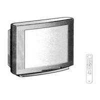
Basic TV control buttons and their functions.

Overview of Remote Control Buttons

Functions of buttons on the remote control.

Using Select Mode

How to select preset picture/sound modes.

Changing Modes Quickly

Quick method to change picture/sound modes.

Additional TV Features

Adjusting the Picture

How to modify picture settings to user preference.

Adjusting the Sound

How to modify sound settings to user preference.

Additional TV Features

Using the Sleep Timer

Setting the TV to switch off automatically after a time.

Viewing Teletext

How to access and use the teletext service.

Additional TV Features

Exchanging Programme Positions

How to change the order of TV channels.

Manually Tuning the TV

Procedure to manually tune TV channels.

Additional TV Features

Fine-Tuning Channels

Procedure to fine-tune channel reception for better picture.

Using Optional Equipment

Connecting and selecting external audio/video equipment.

Connecting External Equipment

Connecting VCR, headphones, decoders, and audio equipment.

Troubleshooting

Specifications

SECTION 2 DISASSEMBLY

Rear Cover Removal

Steps to remove the television's rear cover.

Chassis Assy Removal

Procedure to remove the main chassis assembly.

SECTION 2 DISASSEMBLY

Service Position

How to place the TV in a service-friendly position.

H1 Board Removal

Steps to remove the H1 circuit board.

S1 Board Removal

Steps to remove the S1 circuit board.

SECTION 2 DISASSEMBLY

Picture Tube Removal

Procedures for removing the picture tube assembly.

Removal of Anode-Cap

Steps for safely removing the anode cap.

How to Handle the Anode-Cap

Precautions for handling the anode cap.

SECTION 2 DISASSEMBLY

Removing the Plates

How to remove bottom plates for service access.

Refitting the Plates

Correct procedure for refitting bottom plates.

SECTION 3 SET-UP ADJUSTMENTS

Beam Landing

Adjusting the electron beam for correct picture alignment.

SECTION 3 SET-UP ADJUSTMENTS

Convergence

Adjusting convergence for color purity and alignment.

SECTION 3 SET-UP ADJUSTMENTS

Dynamic Convergence Adjustment

Fine-tuning convergence dynamically.

SECTION 3 SET-UP ADJUSTMENTS

Screen Corner Convergence

Correcting convergence issues in screen corners.

Screen [G2], White balance

Adjusting G2 and white balance for optimal picture.

Focus

Adjusting the focus control for a sharp picture.

SECTION 4 CIRCUIT ADJUSTMENTS

Electrical Adjustments

Performing electrical adjustments using the remote commander.

SECTION 4 CIRCUIT ADJUSTMENTS

Sub Brightness Adjustment

Adjusting sub-brightness for optimal signal levels.

Sub Contrast Adjustment

Adjusting sub-contrast for waveform output.

Sub Colour Adjustment

Adjusting sub-colour for equal color bar levels.

SECTION 4 CIRCUIT ADJUSTMENTS

Bell Filter Adjustment

Adjusting bell filter for Secam models.

Deflection System Adjustment

Adjusting deflection system for optimum image.

SECTION 4 CIRCUIT ADJUSTMENTS

Test Mode 2

Accessing and using Test Mode 2 functions.

SECTION 4 CIRCUIT ADJUSTMENTS

FE-1 Self Diagnostic Software

Software for identifying and diagnosing FE-1 chassis errors.

SECTION 5 DIAGRAMS

Block Diagram

Overall block diagram of the TV system.

SECTION 5 DIAGRAMS

Block Diagrams (2)

Further block diagrams of specific sections.

SECTION 5 DIAGRAMS

Circuit Board Location

Location of circuit boards within the TV.

Schematic Diagrams and Printed Wiring Boards

Detailed schematics and PWB layouts.

Component Identification

Semiconductors and IC blocks listing.

S1 BOARD

S1 Board < Component Side >

Component layout of the S1 board.

S1 Board IC Voltage Table

Voltage table for ICs on the S1 board.

S1 Board Transistor Voltage Table

Voltage table for transistors on the S1 board.

A BOARD

A Board Transistor Voltage Table

Voltage table for transistors on the A board.

A Board IC Voltage Table

Voltage table for ICs on the A board.

A BOARD

Component Identification Reference Information

Reference information for component symbols.

Schematic Diagrams and Printed Wiring Boards

Detailed schematics and PWB layouts.

S1 BOARD

S1 Board < Component Side >

Component layout of the S1 board.

S1 Board IC Voltage Table

Voltage table for ICs on the S1 board.

S1 Board Transistor Voltage Table

Voltage table for transistors on the S1 board.

S1 BOARD

S1 Board Mark

Markings and component data for the S1 board.

S1 BOARD

S1 Board Mark

Markings and component data for the S1 board.

WAVEFORMS A BOARD

A BOARD MARK

VM

VM Board

Diagram of the VM board and its components.

VM

VM Board

Diagram of the VM board and its components.

Board Component Data

IC/Transistor voltage tables and waveforms for VM/C boards.

C Board

C Board

Diagram of the C board and its components.

H1 Board

H1 Board

Diagram of the H1 board and its components.

5-4. SEMICONDUCTORS

5-5. IC BLOCK DIAGRAMS

SECTION 6 EXPLODED VIEWS

Chassis

Exploded view and part numbers for the chassis assembly.

SECTION 6 EXPLODED VIEWS

Picture Tube

Exploded view and part numbers for the picture tube assembly.

SECTION 7 ELECTRICAL PARTS LIST

Capacitors

List of capacitor part numbers and specifications.

SECTION 7 ELECTRICAL PARTS LIST

Capacitors

List of capacitor part numbers and specifications.

SECTION 7 ELECTRICAL PARTS LIST

Capacitors

List of capacitor part numbers and specifications.

Filter

List of filter components.

Connectors

List of connector part numbers.

SECTION 7 ELECTRICAL PARTS LIST

Diodes

List of diode part numbers.

Ferrite Beads

List of ferrite bead part numbers.

SECTION 7 ELECTRICAL PARTS LIST

Transistors

List of transistor part numbers.

ICs

List of IC part numbers.

Coils

List of coil part numbers.

SECTION 7 ELECTRICAL PARTS LIST

Transistors

List of transistor part numbers.

Resistors

List of resistor part numbers.

SECTION 7 ELECTRICAL PARTS LIST

Transistors

List of transistor part numbers.

Resistors

List of resistor part numbers.

SECTION 7 ELECTRICAL PARTS LIST

Resistors

List of resistor part numbers.

SECTION 7 ELECTRICAL PARTS LIST

Resistors

List of resistor part numbers.

Crystals, Relays, Switches

Lists for crystals, relays, and switches.

SECTION 7 ELECTRICAL PARTS LIST

Transistors

List of transistor part numbers.

SECTION 7 ELECTRICAL PARTS LIST

Capacitors, Diodes, ICs, Coils

Lists of common electronic components.

Variable Resistors & Connectors

Lists for variable resistors and connectors.

SECTION 7 ELECTRICAL PARTS LIST

Transistors

List of transistor part numbers.

Resistors

List of resistor part numbers.

SECTION 7 ELECTRICAL PARTS LIST

Resistors

List of resistor part numbers.

ICs, Coils, Capacitors

Lists of ICs, coils, and capacitors.

Sockets

List of socket part numbers.

SECTION 7 ELECTRICAL PARTS LIST

Capacitors

List of capacitor part numbers and specifications.

SECTION 7 ELECTRICAL PARTS LIST

Resistors

List of resistor part numbers.

Crystals

List of crystal part numbers.

SECTION 7 ELECTRICAL PARTS LIST

Miscellaneous

Various parts including cushions, magnets, and transformers.

Accessories and Packaging Materials

Bags, cartons, and remote commander.

Related product manuals