EasyManua.ls Logo

Sony KV-28FX60U User Manual

Sony KV-28FX60U
92 pages
To Next Page IconTo Next Page
Page #1 background imageLoading...
Page #1 background image
1
SERVICE MANUAL AE-5 CHASSIS
MODEL
COMMANDER DEST CHASSIS NO.
MODEL
COMMANDER DEST CHASSIS NO.
KV-28FX60A
RM-891 Italian SCC-Q12D-A
KV-28FX60B
RM-891 French SCC-Q13D-A
KV-28FX60D
RM-891 AEP SCC-Q11D-A
KV-28FX60E
RM-891 Spanish SCC-Q14D-A
KV-28FX60K
RM-891 OIRT SCC-Q16F-A
KV-28FX60R
RM-891 OIRT SCC-Q16E-A
KV-28FX60U
RM-891 UK SCC-Q15C-A
KV-32FX60A
RM-891 Italian SCC-Q12B-A
KV-32FX60B
RM-891 French SCC-Q13B-A
KV-32FX60D
RM-891 AEP SCC-Q11B-A
KV-32FX60E
RM-891 Spanish SCC-Q14B-A
KV-32FX60K
RM-891 OIRT SCC-Q16A-A
KV-32FX60R
RM-891 OIRT SCC-Q16B-A
KV-32FX60U
RM-891 UK SCC-Q15B-A
®
MICROFILM
TRINITRON
®
COLOR TV
Question and Answer IconNeed help?

Do you have a question about the Sony KV-28FX60U and is the answer not in the manual?

Sony KV-28FX60U Specifications

General IconGeneral
Screen Size28 inches
Display TypeCRT
Aspect Ratio4:3
Audio Output20 W
TunerAnalog
ResolutionStandard Definition
ConnectivitySCART x 2, Composite Video, S-Video
TV StandardPAL, SECAM
FeaturesTeletext

Summary

TV Specifications and Connectivity

Input/Output Terminals

Description of the TV's input and output connectors, including Scart and audio jacks.

Remote Control and Feature Specifications

Model-Specific Feature Settings

Table detailing features like Pal Comb, PIP, and Teletext availability per model.

Electrical Safety Warning

Important safety information regarding mains lead, plug, and fuse replacement.

21-Pin Connector Pinout and Signal Details

21-Pin Connector Pin Assignments

Details the pin numbers and their corresponding signal names for the 21-pin connector.

Signal Levels and Descriptions

Explains the signal levels, impedance, and functions for each pin connection.

AE-5 Self-Diagnostic Software

Error Identification and Detection

Explains error detection via LED flashes and IIC communication failures.

Diagnostic Item Descriptions

Lists diagnostic items, LED flashes, probable causes, and detected symptoms.

Error Code List

Provides a list of error codes and their corresponding LED error counts.

Error Monitoring and Reporting

IIC and Board Error Detection Methods

Describes error detection methods: IIC line, board checks, and individual device checks.

Error Monitor Menu Display

Explains how to access and interpret the Error Monitor Menu for saved and actual errors.

Error Reader Display and Codes

Error Code Transmission to Reader

Details data sent to the service error reader for actual error code retrieval.

Error Code Interpretation Table

Lists error codes, their types (Gen.IIC, Board, Device), and associated functions.

General Cautions and Warnings

Anode Safety Precautions

Critical warning about short-circuiting the picture tube anode before removal.

Electrical Shock Hazard Warning

Warning about using an isolating transformer due to live chassis for service.

Safety-Related Component Identification

Notes on critical components identified by shading and marks for safety.

Initial TV Setup and Basic Operation

Connecting TV and Peripherals

Instructions for connecting the TV to mains, aerial, or external devices like VCRs.

Automatic Channel Tuning

Process for automatically tuning in available channels for immediate use.

Advanced TV Presetting Features

Manual Channel Tuning

Guide for manually tuning individual channels or input sources to specific positions.

Advanced Presetting Customization

Further Programme Preset Options

Adjusting volume offset, fine-tuning, and AV output for specific channels.

Advanced Picture Adjustments

Advanced Picture and Sound Settings

Picture Control Adjustments

Detailed settings for Picture Mode, Contrast, Brightness, Colour, Hue, Sharpness, and Noise Reduction.

Sound Control Adjustments

Detailed settings for Equaliser Mode, Balance, Loudness, Space, and Dual Sound.

Advanced TV Features and PIP

Picture-in-Picture (PIP) Operation

How to use PIP, switch it on/off, select sources, swap screens, and change PIP position.

Teletext Functions and Operation

Teletext Menu System

Using the menu-guided teletext system for Top/Bottom/Full view, Text Clear, Reveal, and Time Page.

Disassembly Procedures

Rear Cover and Chassis Assembly Removal

Steps for removing the rear cover and the chassis assembly.

Service Position and U Board Removal

Procedures for placing the TV in service mode and removing the U board.

Component Board Disassembly

Picture Tube and Anode Cap Handling

Picture Tube and Anode Cap Removal

Detailed steps for removing the picture tube and its anode cap.

Anode Cap Handling Precautions

Important notes on safely handling the anode cap to prevent damage.

Main-Bracket Bottom Plate Procedures

Set-Up Adjustments Procedures

Beam Landing Preparation

Steps required before starting beam landing adjustment, including degaussing.

Y-Splitting Axis Magnet Adjustment

Adjusting the correction magnet for the Y-splitting axis.

Beam Landing Adjustment Steps

Detailed steps for landing beam adjustment, including green pattern alignment.

Convergence Adjustment

Screen Center Static Convergence

Procedures for static convergence adjustment at the screen center.

Advanced Convergence Corrections

V.STAT Magnet Adjustment for Convergence

Adjusting V.STAT magnet for red, green, blue dot convergence.

Hexapole Magnet for Mis-convergence Correction

Using Hexapole magnet for horizontal and vertical mis-convergence correction.

Focus and White Balance Adjustments

Focus Adjustment

Steps to adjust the focus control for optimal picture sharpness.

Screen (G2) and White Balance Adjustment

Procedures for G2 adjustment and white balance using service mode.

White Balance and Backend Settings

White Balance Adjustment for TV Mode

Detailed steps for adjusting white balance for optimal picture quality.

Backend Parameter Settings

Table listing backend parameters with adjustable ranges and default values.

Electrical Adjustments and Service Mode

Entering Service Mode

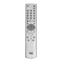
Instructions on how to access the TV's service mode using the remote commander.

Service Menu Navigation and Options

Overview of the service menu structure and its main sections (Initialising, Monitoring, Reset Devices).

Service Mode Settings Configuration

Backend Parameter Details

Detailed list of backend parameters with adjustable ranges and default values.

Service Mode: Feature, Deflection, and Decoder Settings

Deflection Settings

Adjustable parameters related to the TV's deflection system.

Dynamic Convergence Settings

Adjustable parameters for fine-tuning dynamic convergence.

Advanced Feature Low-End Settings

Feature Low-End Parameter Table

Extensive table detailing various 'Feature Low-End' parameters and their settings.

PIP and Advanced Feature Settings

Advanced Feature Settings (Low-End Cont.)

Continuation of 'Feature Low-End' settings, including PIP related options.

Sound and Special Adjustment Parameters

Special Adjustment Parameters

Parameters for special adjustments like RGB levels, EPG check, and audio settings.

Deflection and Volume Adjustments

Deflection System Adjustment

General guide for adjusting the deflection system to obtain optimum image.

Test Mode 2 Functions

Test Mode 2 Function List

Comprehensive list of functions available in Test Mode 2, identified by numerical codes.

System Diagrams and Board Layouts

Schematic Diagrams and Printed Wiring Boards

Reference to detailed schematic diagrams and printed wiring board layouts.
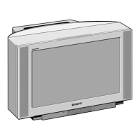
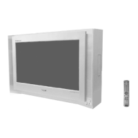
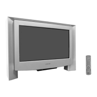
Circuit Board Location Details

B1 Board: 100Hz Digital Plus

VM Board: Velocity Modulation

D1 Board: Deflection System

M Board: Micro and Text Features

E Board: RGB Output and Chroma Details

D Board: Power Supply and Deflection

Semiconductor Components Identification

Semiconductor Components Identification (Continued)

IC Block Diagrams

Exploded Views: Chassis Components

Chassis Component Identification (Continued)

Exploded View: Picture Tube Assembly

Picture Tube Assembly Components (Continued)

Electrical Parts List: B1 Board Capacitors

Electrical Parts List: B1 Board Components

Electrical Parts List: B1, F, and F1 Boards

Electrical Parts List: A Board Capacitors and Connectors

Electrical Parts List: A Board ICs and Resistors

Electrical Parts List: AM Board Components

Electrical Parts List: M Board Components

Electrical Parts List: M Board Components (Continued)

Electrical Parts List: D Board Resistors

Electrical Parts List: D1 Board Components

Electrical Parts List: D1 Board Transistors and ICs

Electrical Parts List: D1 Board Resistors (Continued)

Electrical Parts List: D Board Capacitors and Connectors

Electrical Parts List: D Board Diodes, Ferrite Beads, and ICs

Electrical Parts List: D Board Transistors and Resistors

Electrical Parts List: D Board Resistors (Continued)

Electrical Parts List: E Board Components

Electrical Parts List: E Board Resistors

Electrical Parts List: E Board Resistors (Continued)

Electrical Parts List: H1, U, and J Boards

Electrical Parts List: J Board Capacitors, Connectors, Jacks, and Diodes

Electrical Parts List: J Board Filters, ICs, and Transistors

Electrical Parts List: J Board Resistors (Part 1)

Electrical Parts List: J Board Resistors (Part 2)

Electrical Parts List: J Board Miscellaneous and Accessories

Related product manuals