EasyManua.ls Logo

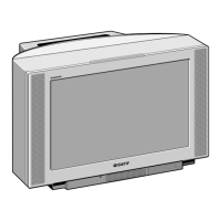
Sony KV-28FX60E User Manual

Sony KV-28FX60E
92 pages
To Next Page IconTo Next Page
Page #1 background imageLoading...
Page #1 background image
1
SERVICE MANUAL AE-5 CHASSIS
MODEL
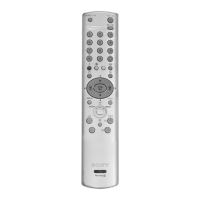
COMMANDER DEST CHASSIS NO.
MODEL
COMMANDER DEST CHASSIS NO.
KV-28FX60A
RM-891 Italian SCC-Q12D-A
KV-28FX60B
RM-891 French SCC-Q13D-A
KV-28FX60D
RM-891 AEP SCC-Q11D-A
KV-28FX60E
RM-891 Spanish SCC-Q14D-A
KV-28FX60K
RM-891 OIRT SCC-Q16F-A
KV-28FX60R
RM-891 OIRT SCC-Q16E-A
KV-28FX60U
RM-891 UK SCC-Q15C-A
KV-32FX60A
RM-891 Italian SCC-Q12B-A
KV-32FX60B
RM-891 French SCC-Q13B-A
KV-32FX60D
RM-891 AEP SCC-Q11B-A
KV-32FX60E
RM-891 Spanish SCC-Q14B-A
KV-32FX60K
RM-891 OIRT SCC-Q16A-A
KV-32FX60R
RM-891 OIRT SCC-Q16B-A
KV-32FX60U
RM-891 UK SCC-Q15B-A
®
MICROFILM
TRINITRON
®
COLOR TV
Question and Answer IconNeed help?

Do you have a question about the Sony KV-28FX60E and is the answer not in the manual?

Sony KV-28FX60E Specifications

General IconGeneral
Screen Size28 inches
Display TypeCRT
Aspect Ratio4:3
Audio Power Output2 x 7W
TV StandardPAL/SECAM
TeletextYes
TunerAnalog
Speaker2 speakers
Input PortsScart, Composite, S-Video

Summary

Service Manual AF-5 Chassis

Model Identification

Lists TV models and their associated chassis numbers for service.

Model Specifications and System Details

21-Pin Connector Pinout and Signals

AE-5 Self-Diagnostic Software

Error Codes and Symptoms

Lists diagnostic items, probable causes, and detected symptoms.

Error Detection Monitor and Reader

General Safety Warnings

Safety-Related Components

Highlights critical components requiring specific replacement procedures.

First Time Operation and Basic Presetting

Automatic Channel Tuning

Guides through the automatic channel scanning process.

Advanced Presetting: Channel Management

Advanced TV Operation: Picture and Sound Control

Advanced TV Operation: Features and PIP

Teletext Operations and Menus

Section 2: Disassembly Procedures

Disassembly: Board and Shield Removals

Disassembly: Picture Tube Removal Procedures

Anode-Cap Handling and Removal

Details safe handling and removal of the anode cap.

Section 3: Set-Up Adjustments

3-1. Beam Landing Adjustments

Guides on adjusting beam landing and purity magnets for picture alignment.

3-2. Convergence Adjustment Procedures

Screen Centre Convergence [Static]

Details static convergence adjustment for screen center.

Convergence Adjustment: Horizontal and Vertical Mis-convergence

Hexapole Magnet Correction

Explains horizontal and vertical mis-convergence correction using the hexapole magnet.

3-3. Focus and 3-4. Screen (G2) White Balance

White Balance Adjustment and Backend Settings

Section 4: Circuit Adjustments

Electrical Adjustments and Service Mode Entry

Explains how to enter service mode and perform electrical adjustments.

Service Menu: Model, Basic, and Backend Settings

Service Menu: Colour Decoders and Feature Settings

Deflection System and Volume Adjustments

Test Mode 2 Functions

Circuit Board Location and Schematic Diagrams

Section 6: Exploded Views

6-1. Chassis Exploded View and Parts List

Provides an exploded view of the chassis and a list of associated parts.

Chassis Exploded View and Parts List (Continued)

6-2. Picture Tube Exploded View and Parts List

Picture Tube Components and Part Numbers

Details components related to the picture tube assembly and their part numbers.

Picture Tube Components (Continued)

Section 7: Electrical Parts List

Electrical Parts List: B1 Board Components

Electrical Parts List: B1 and F1 Board Components

Related product manuals