EasyManua.ls Logo

Sony KV-29FX60A RM-891 User Manual

Sony KV-29FX60A RM-891
92 pages
To Next Page IconTo Next Page
Page #1 background imageLoading...
Page #1 background image
1
SERVICE MANUAL AE-5
CHASSIS
MODEL
COMMANDER DEST CHASSIS NO.
MODEL
COMMANDER DEST CHASSIS NO.
®
KV-29FX60A
RM-891 Italian SCC-Q12A-A
KV-29FX60B
RM-891 French SCC-Q13A-A
KV-29FX60D
RM-891 AEP SCC-Q11A-A
KV-29FX60E
RM-891 Spanish SCC-Q14A-A
KV-29FX60U
RM-891 UK SCC-Q15A-A
MICROFILM
TRINITRON
®
COLOR TV
Question and Answer IconNeed help?

Do you have a question about the Sony KV-29FX60A RM-891 and is the answer not in the manual?

Sony KV-29FX60A RM-891 Specifications

General IconGeneral
BrandSony
ModelKV-29FX60A RM-891
CategoryTV
LanguageEnglish

Summary

Safety Warnings and Cautions

Warning and Caution Notes

Critical safety warnings and cautions for service personnel.

SECTION 1 GENERAL

Overview of TV and Remote Controls

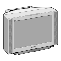
Describes TV set buttons, controls, and remote control functions.

First Time Operation

Installation and Connection Steps

Procedures for connecting the TV set to power, aerial, or devices.

Basic TV Presetting

Initial setup including language, country, and auto tuning.

Advanced Operation

Advanced Presetting Options

Customizing channel order, names, and fine-tuning settings.

Manual Channel Tuning

Manually setting channels or video input sources.

Teletext Functions

Direct Access and Page Selection

Methods for accessing teletext pages and functions.

Teletext Menu Operations

Navigating teletext menus for text clear, reveal, and time page.

SECTION 2 DISASSEMBLY

Rear Cover and Chassis Removal

Procedures for removing the rear cover and chassis assembly.

Board Removal Procedures

Step-by-step guide for removing internal boards like U, J, B2.

Picture Tube and Anode Cap Handling

Instructions for removing the picture tube and handling the anode cap.

SECTION 3 SET-UP ADJUSTMENTS

Beam Landing and Purity Adjustment

Adjusting beam landing, purity, and Y-splitting axis correction.

Convergence Adjustment Details

Screen center and static convergence adjustments using magnets.

Focus and White Balance Adjustment

Adjusting picture focus and white balance using service mode.

SECTION 4 CIRCUIT ADJUSTMENTS

Electrical Adjustments (Service Mode)

Entering service mode and adjusting various electrical parameters.

Deflection System and Test Modes

Adjusting deflection system and utilizing test modes.

SECTION 5 DIAGRAMS

Block Diagrams Overview

High-level block diagrams illustrating system architecture.

Circuit Board Locations

Visual layout of circuit boards within the TV chassis.

Semiconductors and IC Block Diagrams

Lists of semiconductors and block diagrams of key ICs.

SECTION 6 EXPLODED VIEWS

Chassis Assembly Exploded View

Exploded diagram of the TV chassis for parts identification.

Picture Tube Assembly Exploded View

Exploded diagram of the picture tube assembly and components.

SECTION 7 ELECTRICAL PARTS LIST

B2 Board Component List

List of components for the B2 circuit board.

D Board Component List

List of components for the D circuit board.

J Board Component List

List of components for the J circuit board.

Correction Bulletins

D Board PWB Layout Error Correction

Notice regarding a printing error in the D board PWB layout.

D [POWER SUPPLY AND DEFLECTION]

Related product manuals