Do you have a question about the Sony TRINITRON KV-29FX11E and is the answer not in the manual?
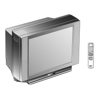
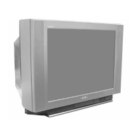
Details about the TV's picture tube, including type and deflection angle.
Lists and describes the input/output terminals located on the front panel.
Lists and describes the input/output terminals located on the rear panel.
Specifications and details for the RM-886 remote control system.
Specific safety warning applicable only to the KV-29FX11U model.
Step-by-step guide for safely replacing the fuse in the TV.
Detailed pin assignment and signal information for the 21-pin connector.
General caution for handling components and avoiding short circuits.
Specific warning about using an isolating transformer for safety during service.
Identifies critical components marked for safe operation and replacement.
Overview of general information and basic operation from the operating manual.
Identification of buttons and layout of the RM-886 remote control.
Lists and explains the function of TV set buttons and input/output terminals.
Explains the functions of the remote commander buttons and their corresponding pages.
Instructions for connecting the aerial to the TV set.
Recommendations for connecting and tuning a VCR signal.
Guide on how to insert batteries into the remote control.
Process for automatically searching and storing TV channels.
Explains operations like switching on/off, selecting programmes, and adjusting volume.
How to switch between different video input sources.
Instructions for accessing and using teletext services.
How to use the remote commander to access and adjust TV functions via the menu.
Instructions for changing the language displayed in the TV menu.
Step-by-step guide for manually tuning and storing TV channels.
Detailed guide for adjusting contrast, brightness, colour, sound modes, and balance.
Method to quickly switch between preset picture modes without entering the main menu.
Steps to manually adjust picture reception when AFT is insufficient.
Guide on exchanging channel positions for better organization.
How to prevent children from watching unsuitable broadcasts by blocking channels.
Setting the TV to automatically switch to standby mode after a specified period.
Correcting picture slant caused by earth magnetism.
How to skip unused channels when using PROGR+/- buttons.
Assigning custom names (up to five characters) to channels or input sources.
Guide on how to activate and deactivate teletext display.
Explains additional teletext features like page access and hidden info reveal.
Storing and displaying frequently used teletext pages for quick access.
Utilizing the Fastext feature for quick page access based on color-coded menus.
Information on connecting external audio/video devices and headphones.
Explains how to select output signals and view inputs using direct access or menu.
Method to select input signals using direct access buttons.
Using the Video Connection menu to select input or output signals.
How to label input sources with custom names (up to five characters).
Provides solutions for problems like no picture, poor picture, no sound, or remote commander issues.
Instructions for removing the rear cover of the television.
Steps for removing the main chassis assembly from the TV.
How to place the TV in a service position for internal access.
Alternative method for positioning the TV for service.
Guidance on managing and routing internal wiring during disassembly.
Instructions for safely removing the 'A' board from the chassis.
Steps for removing the 'A' extension board.
Detailed steps for safely removing the picture tube assembly.
Specific instructions and safety precautions for removing the anode cap.
Guidelines for safely handling the anode cap to prevent damage.
Steps for cutting gates and removing the bottom plates.
Guide on correctly identifying and refitting the bottom plates.
Steps for adjusting beam landing using purity controls and magnets.
Adjusting static convergence using H.STAT and V.STAT magnets.
Adjusting convergence dynamically using deflection yolk tilt and BMC magnets.
Correcting screen corner convergence issues using permalloy assemblies.
Steps for adjusting white balance using G2 settings and CRT cathode voltages.
Procedure for adjusting the picture focus for optimal sharpness.
Overview of electrical adjustments accessible via service mode.
Steps required to access the TV's service mode using the remote commander.
How to adjust the sub-brightness setting for optimal picture quality.
Procedure for adjusting the sub-contrast to achieve proper black-to-white amplitude.
Steps for adjusting sub-colour for accurate colour reproduction.
Adjusting the IF frequency for specific broadcast systems.
Adjusting the IF frequency for the L Band 1 system.
Adjusting the Automatic Gain Control for the tuner.
Adjusting various geometry parameters like V size, H position, and pin amp.
Lists and describes various test modes for carrier, picture, volume, aging, and system settings.
Details functions from 66-99 including DSP bypass, diagnostics, sound center modes, and text acquisition delay.
Explains how the chassis identifies and reports device failures or busy bus conditions.
First part of the block diagram illustrating system connections.
Second part of the block diagram showing system interconnections.
Third part of the block diagram detailing system components.
Diagram showing the physical placement of major circuit boards within the TV.
Provides schematic diagrams and printed wiring board layouts for system components.
Diagrams and waveform data relevant to the C circuit board.
Diagrams and waveform data relevant to the D circuit board.
Schematic and IC voltage data for the A board.
Schematic and transistor voltage data for the A board.
Visual representation of waveforms for various signals on the A board.
Voltage tables for ICs and components on the A board.
Diagrams and transistor voltage table for the VM board.
Diagrams and transistor voltage table for the D5 board.
Diagrams and IC voltage table for the K5 board.
Waveform illustrations for various signals on the D board.
Waveform illustrations for various signals on the C board.
Waveform illustrations for various signals on the A board.
Block diagrams for ICs on the A board (CXA2076, MSP3410D, CXA2040AQ, PST593C).
Block diagrams for ICs on the D board (STV9379, TDA7264, STR-S6709).
Visual representations of IC package outlines and pinouts.
Diagrams and identification for transistors, diodes, and other semiconductor parts.
Diagrams and part numbers for various diodes and transistors.
An exploded view diagram of the TV chassis, showing the arrangement of major components.
Detailed exploded view and part list for the picture tube and related parts.
List of capacitors used on the A board with reference numbers and specifications.
List of A board capacitors from C225 to C355 with part numbers.
Parts list for connectors, diodes, ICs, and coils on the A board.
Parts list for transistors and resistors on the A board.
List of A board resistors from R20 to R86 with part numbers and values.
List of A board resistors from R87 to R255 with part numbers and values.
List of A board resistors from R256 to R370 with part numbers and values.
Parts list for resistors and ICs on the IF board.
Parts list for tuners, crystals, connectors, filters, diodes, transistors, and variable resistors on the IF board.
Parts list for capacitors, filters, and trimmers on the IF board.
Parts list for ICs, coils, transistors, and resistors on the IF board.
Parts list for capacitors, connectors, and diodes on the C board.
Parts list for ICs, coils, transistors, and resistors on the C board.
Parts list for spark gaps, capacitors, and connectors on the D5 board.
Parts list for diodes, ICs, coils, transistors, and resistors on the D5 board.
Parts list for D board resistors from R2821 to R2858 with specifications.
Parts list for D board capacitors from C502 to C601A with specifications.
List of D board capacitors from C630 to C908 with specifications.
Parts list for connectors, ICs, and diodes on the D board.
Parts list for diodes and fuses on the D board.
Parts list for ferrite beads, ICs, sockets, coils, and transistors on the D board.
Parts list for resistors, IC links, and transistors for the D board.
Parts list for IC links, transistors, and resistors on the D board.
Continues the resistor list for the D board.
Parts list for relays, switches, and spark gaps on the VM board.
Parts list for transformers, thermistors, capacitors, and IC links on the VM board.
Parts list for transistors on the VM board.
Parts list for resistors and capacitors on the K5 board.
List of various miscellaneous parts like coils, magnets, transformers, and speakers.
List of included manuals, cartons, and packing items.
Part number for the standard remote commander (RM-886).