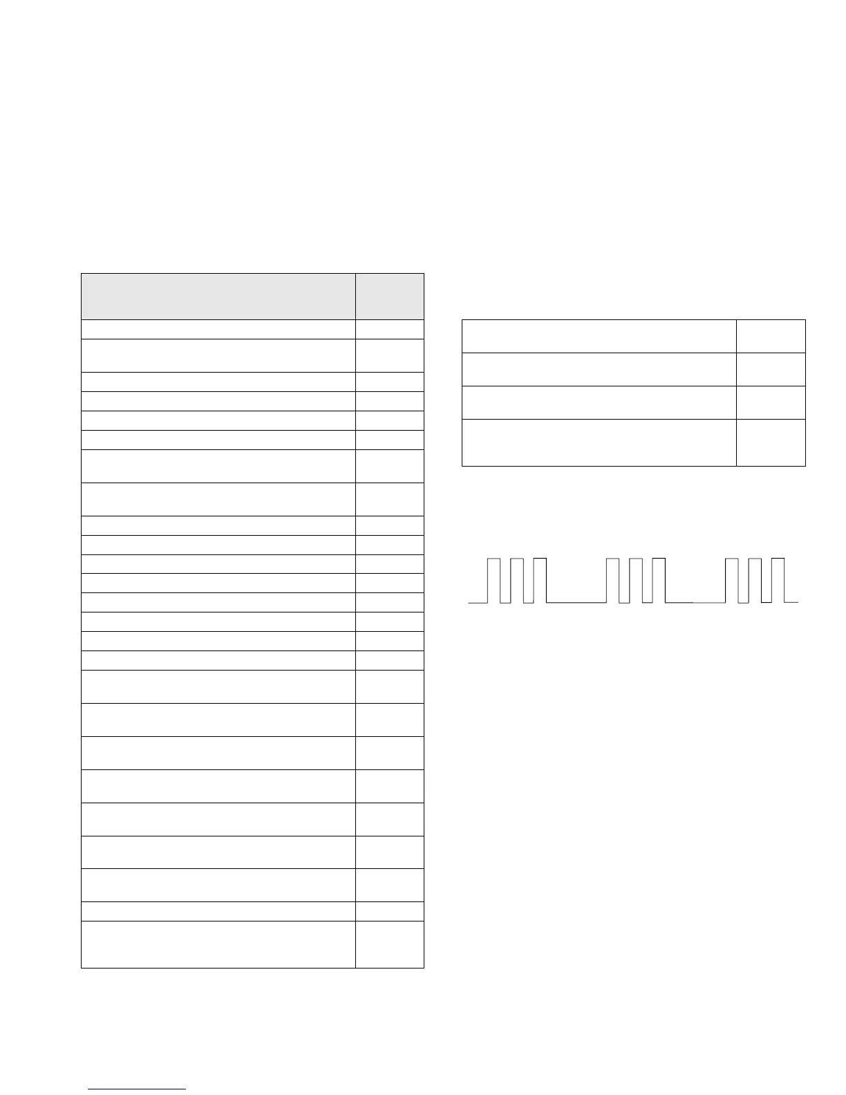
33
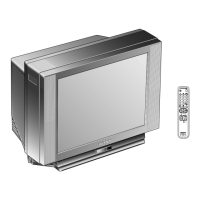
KV-29FX11
StBy LED
ON ON ON
OFF OFF
Flash Timing Example : e.g. error number 3
ERROR
LED
ERROR
COUNT
No error 00
Not allowed (may be confused with Sircs response
flash!)
01
Protection circuit trip < ANY TIME > 02
IIC SCL LOW < POWER UP ONLY > 03
IIC SDA LOW < POWER UP ONLY > 04
IIC SDA & SCL LOW < POWER UP ONLY > 05
Jungle / Chroma controller no acknowledge
< POWER UP ONLY >
06
Video Switch no acknowledge
< POWER UP ONLY >
07
Tuner no acknowledge 08
MSP no acknowledge 09
NVM no acknowledge 10
M3L TXD Low < POWER UP ONLY > 11
M3L RXD Low < POWER UP ONLY > 12
M3L ENABLE Low < POWER UP ONLY > 13
M3L TXD & RXD Low < POWER UP ONLY > 14
Compact Text test fail < POWER UP ONLY > 15
AV switch cannot power on reset
< Chassis Initialisation >
16
Cannot initialise jungle ( after initial power on
checked out OK ) - < Chassis initialisation >
17
NVM acknowledge fail after initialisation (STBY +5V
same as micro!)
18
Multiple devices with no acknowledge
< POWER UP ONLY >
19
Compact text run-time failure after power up check
(+9V test)
20
AV SWITCH response failure after power up check
(+9V test)
21
JUNGLE / CHROMA controller response failure
after power up check (-9V test)
22
Compact text does not respond (-5V test) 23
MSP run-time failure
< MAY NOT BE FATAL-DISPLAY ON ERROR
READER >
24
M3L bus Clock low time out after data send
( run-time failure)
25
M3L bus Clock low time out after data send
( at power up check )
26
M3L bus Clock low time out after data send
( at initialisation )
27
DSP run-time failure
< MAY NOT BE FATAL-DISPLAY ON ERROR
READER >
28
4-3. BE-3D SELF DIAGNOSTIC SOFTWARE
The identification of errors within the BE-3D chassis is triggered in one of two ways :- 1: Busy busy or 2: Device failure to respond to IIC. In the
event of one of these situations arising the software will first try to release the bus if busy [Failure to do so will report with continuous flashing
LED] and then communicate with each device in turn to establish if a device is faulty. If a device is found to be faulty the relevant device number
will be displayed through the LED [Series of flashes which must be counted] See Table 1., non fatal errors are reported using this method.