5
LOCATION
AND
FUNCTION
OF
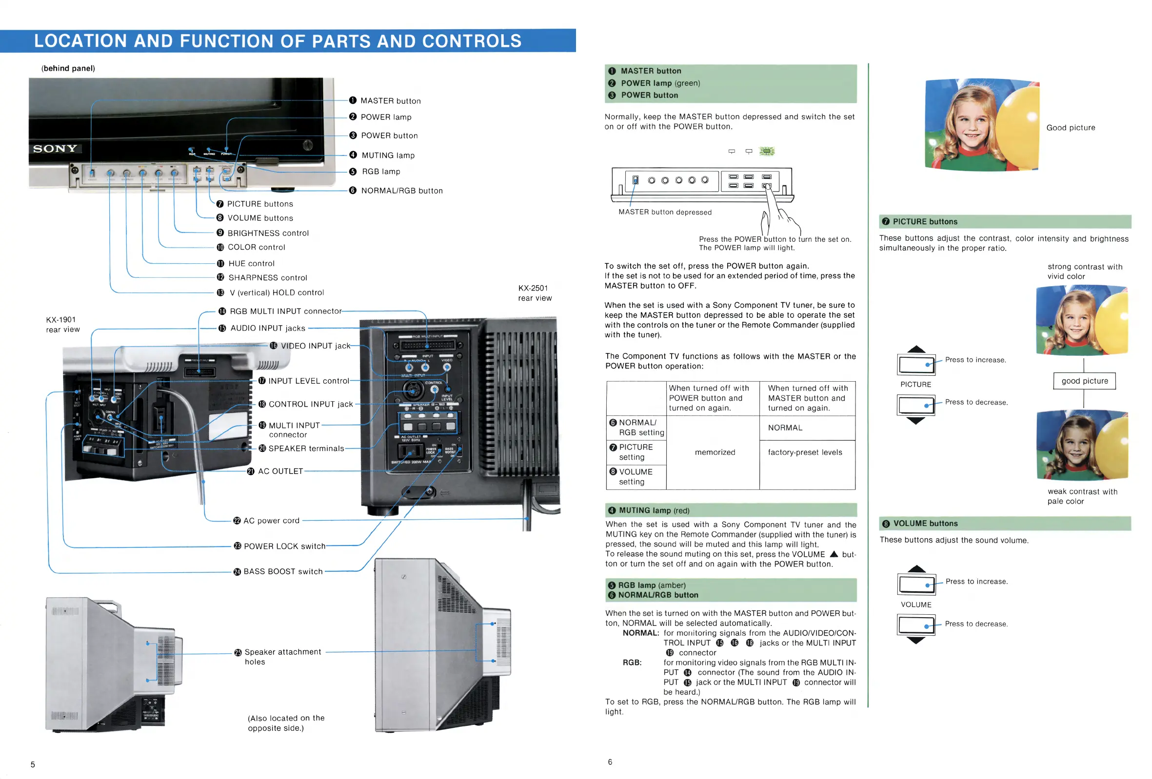
PARTS AND CONTROLS
(behind panel)
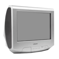
KX-1901
rear view
0 MASTER
button
8 POWER lamp
@ POWER
button
0 MUTING
lamp
-------'--
0 RGB
lamp
f)
PICTURE
buttons
@ VOLUME
buttons
'--
--
0 BRIGHTNESS
control
----
-
41)
COLOR
control
--
- -
---
48
HUE
control
--
-
-----
40
SHARPNESS
control
- -
--------
411
V (vertical) HOLD
control
ti) RGB MULTI INPUT connector·
----------...
----------
--
Cl)
AUDIO INPUT
jacks
-----
-
----
-=
'---t-
-==
=~ae=:
:::.
~ VIDEO INPUT
jack
J)))))J)
4D
INPUT LEVEL
control
«;)
CONTROL INPUT
jack
@>
MUL Tl INPUT
---
connector
W SPEAKER
terminals
{
I
G:
I i.
I
,,
-
RG8Ml,LTll"ll>,JT
-
··
-
INPUT
-
•
:-
'"'
!"'
"-
l
'IIOEO
0
0
0
;
.:
-~':':
....
-·
I
CONTROl
(
\
0
INPIJT
·
lEVEl
--..
"'""°'"c"'c'a-ll!IOl
-
61•e
e ,
61
--·
...
-
• :
•
-
-
•
-
ACOUlL~T
-
120"
e0t1,
....
u
....
,OCK
"'°"
SWIT~1EO
200W
MA)'
,.
/
,
'
,..
/--
,
..
.
11
•
•
•
•
I I
•
..
.
.
.,
.,.
.,.
r
..
.
..
.
r
r
I I
r -
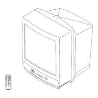
KX-2501
rear view
, t
i:-
..
r
id
I
I
'·I
I
t
:''
:11
~.
I
I I
--
- - - -
'
1
~
0 AC
power
cord
--------:-'.:__~:__
__________
-t11
'---------------
@}
POWER LOCK
switch
_/
'--------
-
---------
~ BASS BOOST
switch
---'
llilll
ll/1#
lll
l
ll/
11
J
--+----
--
f})
Speaker
attachment
----
---4
+----
H
----
;a
holes
(Also located on the
opposite
side.)
0 MASTER button
8 POWER lamp (green)
@
POWER button
Normally
, keep the MASTER
button
depressed and
switch
the
set
on or
off
with
the POWER
button.
MASTER
button depressed
Press the
POWER
button to turn the set
on.
The
POWER
lamp will light.
To
switch
the
set
off,
press
the
POWER
button
again.
If
the set is
not
to
be used
for
an
extended
period
of
time
, press the
MASTER
button
to
OFF.
When the set
is
used
with
a Sony
Component
TV tuner, be sure
to
keep the MASTER
button
depressed
to
be able
to
operate
the
set
with
the
controls
on
the
tuner
or
the
Remote
Commander
(supplied
with
the tuner).
The
Component
TV
functions
as
follows
with
the MASTER
or
the
POWER
button
operation:
When
turned
off
with
When turned
off
with
POWER
button
and MASTER
button
and
turned on again.
turned
on again.
0 NORMAL/
NORMAL
RGB setting
@ PICTURE
memorized factory-preset levels
setting
@VOLUME
setting
0 MUTING lamp (red)
When the set is used with a Sony Component
TV
tuner and the
MUTING key on the Remote
Commander
(supplied with the tuner) is
pressed, the sound will be muted and
this
lamp will light.
To release the sound
muting
on
this
set, press the VOLUME A but-
ton
or
turn the set
off
and on again
with
the POWER
button.
0 RGB lamp (amber)
(i) NORMAURGB button
When the set is turned on
with
the MASTER
button
and POWER but-
ton, NORMAL will be selected
automatically.
NORMAL: for
monitoring
signals from the AUDIO/VIDEO/CON-
TROL INPUT
Cl)
~
«;)
jacks
or the MULTI INPUT
@)
connector
RGB:
for
monitoring
video signals from the
RGB
MULTI IN-
PUT
ti)
connector
(The sound from the AUDIO IN-
PUT
Cl)
jack
or
the MULTI INPUT
@)
connector
will
be heard.)
To set to RGB, press the NORMAL/RGB button. The
RGB
lamp will
light.
6
Good
picture
f)
PICTURE buttons
These
buttons
adjust the contrast, color intensity and brightness
simultaneously
in the proper ratio.
'--------'
=
it
=
Press
to incre
ase.
PICTURE
0 VOLUME buttons
These
buttons
adjust the sound volume.
'--
=
it
= Press to increase.
VOLUME
strong
contrast
with
vivid color
good picture
weak contrast with
pale color
 Loading...