(3)
Assemble the socket.
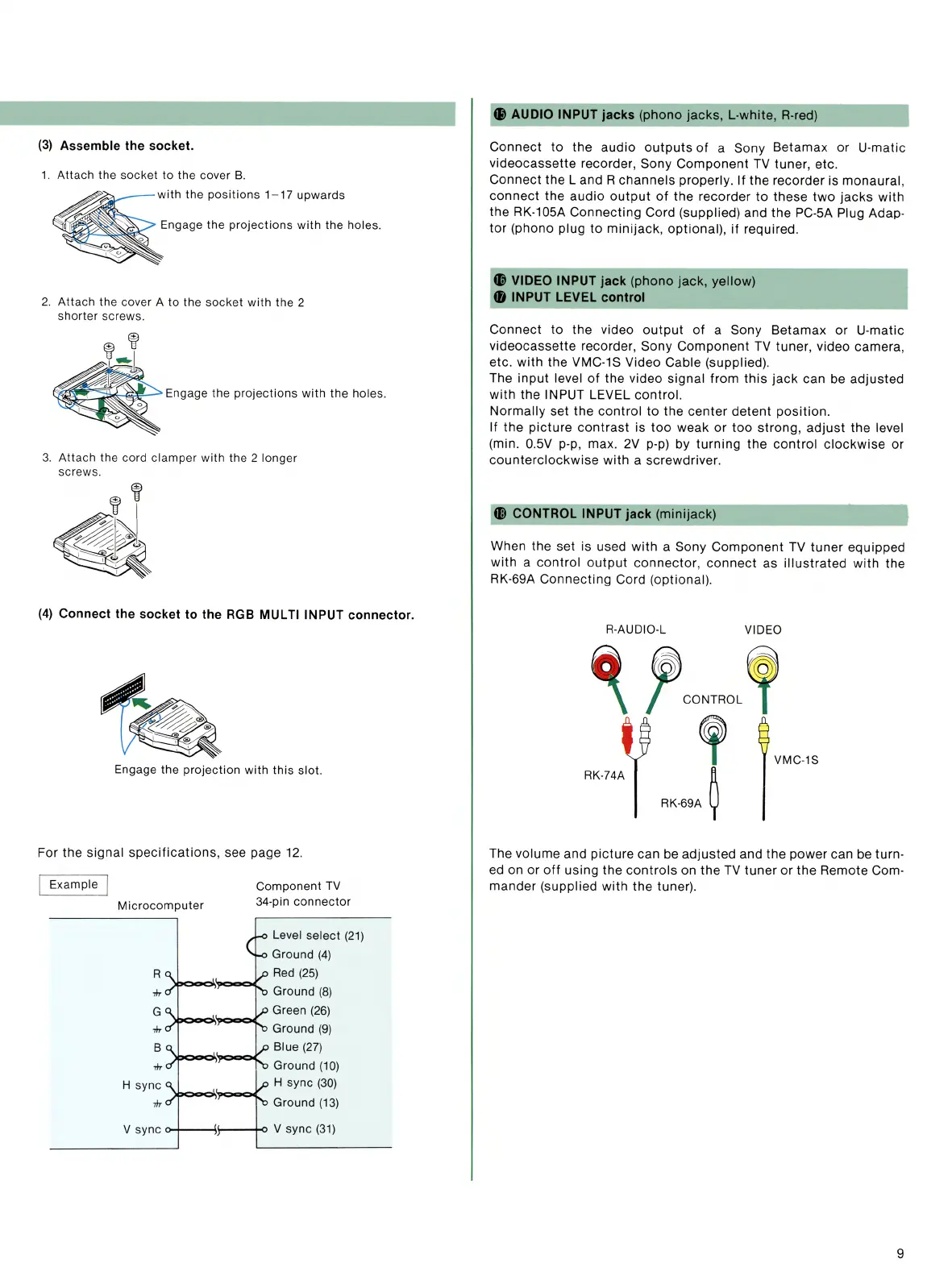
1.
Attach the socket to the cover B.
with the positions
1-17
upwards
Engage the projections with the holes.
2. Attach
th
e
co
ver
A to the socket with the 2
shorter
sc
re
ws.
Engage
the projections with the holes.
3.
Att
ac
h the c
ord
clamper with the 2 longer
sc
r
ews.
(4)
Connect the socket
to
the
RGB
MUL
Tl
INPUT connector.
Engage the projection with this slot.
For the signal
specifications,
see page
12.
Example
Microcomputer
R
,I,.
G
,I,.
B
,I,.
H sync
,I,.
Component
TV
34
-pin connector
Level
select
(21)
Ground
(4)
Red
(25)
Ground
(8)
Green
(26)
Ground
(9)
Blue
(27)
Ground
(10)
H sync
(30)
Ground
(13)
V sync
o-+--,--"T<l
V sync
(31)
49
AUDIO INPUT jacks (phono jacks, L-white, R-red)
Connect
to
the
audio
outputs
of
a Sony
Betamax
or
U-matic
videocassette
recorder, Sony
Component
TV tuner,
etc
.
Connect
the
Land
R
channels
properly.
If
the
recorder
is
monaural,
connect
the
audio
output
of
the
recorder
to
these
two
jacks
with
the RK-105A
Connecting
Cord (supplied) and the PC-5A Plug Adap-
tor
(phono plug
to
minijack,
optional),
if
required.
4D
VIDEO INPUT jack (phono jack, yellow)
•
INPUT LEVEL control
Connect
to
the video
output
of
a Sony
Betamax
or
U-matic
videocassette
recorder, Sony
Component
TV
tuner
, video camera,
etc.
with
the VMC-1S Video Cable (supplied).
The
input
level
of
the video
signal
from
this
jack
can be
adjusted
with
the INPUT LEVEL
control.
Normally
set
the
control
to
the
center
detent
position.
If
the
picture
contrast
is
too
weak
or
too
strong
,
adjust
the level
(min. 0.
5V
p-p, max. 2V p-p) by
turning
the
control
clockwise
or
counterclockwise
with
a screwdriver.
t,
CONTROL INPUT jack (minijack)
---------
When the set
is
used
with
a Sony
Component
TV
tuner
equipped
with
a
control
output
connector
,
connect
as
illustrated
with
the
RK-69A
Connecting
Cord (optional).
R-AUDIO-L
VIDEO
The
volume
and
picture
can be
adjusted
and the
power
can be turn-
ed on or
off
using
the
controls
on
the
TV
tuner
or
the Remote Com-
mander
(supplied
with
the tuner).
9


 To Next Page