Do you have a question about the Sony LBT-DR440 and is the answer not in the manual?
Warns about hazardous radiation, chip components, and flexible circuit board repair.
Outlines post-repair safety checks for AC leakage and critical component replacement.
Provides notes on CD block operation, signal levels, and checks like S Curve.
Detailed block diagram illustrating the optical pick-up and digital servo functions.
Schematic diagram detailing the playback, record, and control circuits of the deck.
Schematic diagram for the main section (1/2), showing control and interface signals.
Schematic diagram for the main section (2/2), detailing power and control ICs.
Schematic diagram detailing the power supply and amplifier circuits for DR series.
Schematic diagram detailing the power supply and amplifier circuits for W/XB series.
Detailed schematic diagram for the BD (CD) section, including ICs and signal paths.
Schematic diagrams for the Trans and Sub Trans boards for W/XB models.
Schematic diagrams for the Trans boards for DR models.
Provides block diagrams for key ICs used in the unit.
| Brand | Sony |
|---|---|
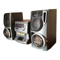
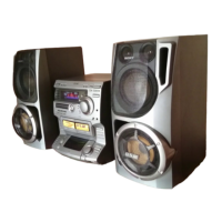
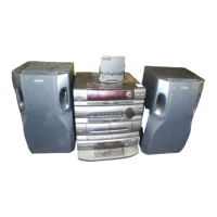
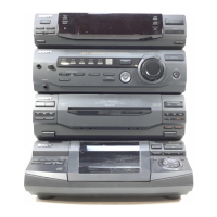
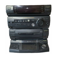
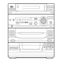
| Model | LBT-DR440 |
| Category | Stereo System |
| Language | English |