Do you have a question about the Sony LBT-DR6 and is the answer not in the manual?
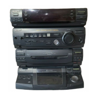
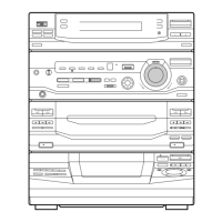
Identifies front panel components and their functions for user operation.
Details procedures for removing the front panel, main board, and mechanisms.
Explains key service modes for diagnostics, reset, and testing functions.
Covers torque measurements, head azimuth, tape speed, and playback level adjustments.
Provides circuit diagrams, block diagrams, and board locations for system sections.
Illustrates physical assembly of chassis, panels, mechanisms, and base units.
Comprehensive list of electronic components required for repair and maintenance.
| Brand | Sony |
|---|---|
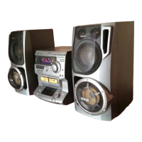
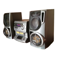
| Model | LBT-DR6 |
| Category | Stereo System |
| Language | English |