EasyManua.ls Logo

Sony LBT-XB500 User Manual

Sony LBT-XB500
90 pages
To Next Page IconTo Next Page
Page #1 background imageLoading...
Page #1 background image
COMPONENT MODEL NAME FOR LBT-DR4/DR5/DR6/DR440/W300/W5000/
XB500
LBT-DR4/DR5/DR6/DR440/
W300/W5000/XB500
US Model
LBT-W300/W5000
Canadian Model
LBT-W300
AEP Model
UK Model
LBT-XB500
E Model
LBT-DR4/DR5/DR6/DR440
Australian Model
LBT-DR4
SERVICE MANUAL
MICROFILM
COMPACT Hi-Fi STEREO SYSTEM
LBT-DR4/DR5/DR6/DR440/W300/W5000/XB500 is composed
following models.
As for the service manual, it is issued for each component model,
then, please refer to it.
General
Power requirements
North American model: 120 V AC, 60 Hz
European model: 230 V AC, 50 / 60 Hz
Mexican model: 120 V AC, 50 / 60 Hz
Australian models: 230 - 240 V AC, 50 / 60 Hz
Other models: 120 V, 220V, or 230 - 240 V AC, 50 / 60 Hz
Adjustable with voltage selector
Power consumption
(LBT-DR6) 220 watts
(LBT-DR5) 200 watts
(LBT-DR440/DR4) 170 watts
(LBT-W5000/W300)
U.S.A. model: 300 watts
Canadian model: 300 VA
(LBT-XB500) 180 watts
SPECIFICATIONS
LBT-DR4 LBT-DR5 LBT-DR6 LBT-DR440 LBT-W300 LBT-W5000 LBT-XB500
COMPACT DISC
DECK RECEIVER
HCD-DR4 HCD-DR5 HCD-DR6 HCD-DR440HCD-W300 HCD-W5000 HCD-XB500
SYSTEM
SPEAKER SYSTEM SS-DR4 SS-DR5 SS-DR6 SS-XB500
Supplied accessories
AM loop antenna (1)
Remote RM-SR5 (1)
R6 (size AA) batteries (2)
FM wire antenna (1)
Speaker cords (2)
Design and specifications are subject to change without notice.

Table of Contents

Question and Answer IconNeed help?

Do you have a question about the Sony LBT-XB500 and is the answer not in the manual?

Sony LBT-XB500 Specifications

General IconGeneral
BluetoothYes
USB PlaybackYes
CD PlayerYes
CD ChangerNo
Cassette DeckNo
TunerYes
FM RadioYes
Remote ControlYes
NFCYes
Speaker SystemBass Reflex
FunctionsBluetooth

Summary

Disassembly Procedures

Service Mode Operations

Mechanical Adjustments

Electrical Adjustments Procedures

Playback Head Azimuth Adjustment

Procedure to adjust azimuth for playback heads on both decks using an oscilloscope and test tape.

Tape Speed Adjustment

Steps to adjust tape speed for deck A using a test mode and specific trimmer adjustments.

Playback Level Adjustment

Procedure to adjust playback levels for both decks using a level meter and specific trimmer adjustments.

Circuit Diagrams and Layouts

BD (CD) Section Block Diagram

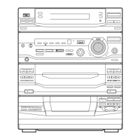
Block diagram illustrating the signal flow and components in the CD section.

BD (CD) Section Schematic Diagram

Schematic diagram detailing the electronic circuitry of the BD (CD) section.

Main Section (1/5) Schematic Diagram

First part of the main section's schematic diagram, illustrating electronic circuits.

Deck Section Schematic Diagram

Schematic diagram for the deck section, detailing audio circuits and controls.

Power Section (1/2) Schematic (DR4 Models)

First part of the power section schematic for specific models.

Power Section (1/2) Schematic (W300 Models)

First part of the power section schematic for W300, W5000, XB500 models.

Panel FL Section Schematic Diagram

Schematic diagram for the Panel FL section, showing its electronic circuitry.

Panel VR Section Schematic Diagram

Schematic diagram for the Panel VR section, detailing its electronic circuits.

TC Panel Section Schematic Diagram

Schematic diagram for the TC Panel section, including TC-B, TC-A, and LED boards.

CD Panel Section Schematic Diagrams

Schematic diagrams for CD-L, CD-R, Front Input, and Door-SW boards.

CD Motor Section Schematic Diagrams

Schematic diagrams for CD Motor, LED (CD), and Table Sensor boards.

Jack Section Schematic Diagrams

Schematic diagrams for the Echo and Jack boards, including MIC AMP circuits.

Trans Section Schematic (W300 Models)

Schematic diagram for the Trans section for W300, W5000, XB500 models.

Trans Section Schematic (DR4 Models)

Schematic diagram for the Trans section for DR4, DR5, DR6, DR440 models.

Exploded Views and Parts

Electrical Parts Lists

Related product manuals