EasyManua.ls Logo

Sony LBT-XG100AV User Manual

Sony LBT-XG100AV
98 pages
To Next Page IconTo Next Page
Page #1 background imageLoading...
Page #1 background image
SERVICE MANUAL
COMPONENT MODEL NAME FOR LBT-XG100AV/XG900AV.
LBT-XG100AV LBT-XG900AV
COMPACT DISC DECK RECEIVER SYSTEM HCD-XG100AV HCD-XG900AV
FRONT SPEAKER SYSTEM SS-XG100AV SS-XG900AV
CENTER SPERAKER SYSTEM SS-CT210
REAR SPEAKER SYSTEM SS-RS210
9-873-814-11 Sony Corporation
2001D0500-1 Home Audio Company
C 2001.4 Shinagawa Tec Service Manual Production Group
Ver 1.0 2001.04
COMPACT Hi-Fi STEREO SYSTEM
AEP Model
UK Model
LBT-XG900AV
E Model
Australian Model
LBT-XG100AV
LBT-XG100AV/XG900AV are composed of following models.
As for the service manual, it is issued for each component
model, then, please refer to it.
ACCESSORIES & PACKING MATERIALS
********************************
1-418-230-11 COMMANDER, STANDARD (RM-SR11AV)
1-501-374-11 ANTENNA, LOOP (AM)
1-501-659-41 ANTENNA (FM) (XG100AV)
1-501-804-11 ANTENNA (FM) (XG900AV)
1-751-347-11 CORD, CONNECTION (10m) (for SS-RS210)
1-769-433-21 CORD, SPEAKER (2.5m) (for SS-CT210)
1-775-512-21 CORD, SPEAKER CONNECTION (2.5m)
(for SS-XG100AV/XG900AV)
4-210-254-01 CUSHION (FOOT) (for SS-XG100AV/XG900AV)
4-233-530-11 MANUAL, INSTRUCTION (ENGLISH)
(XG100AV: AR, AUS/XG900AV: UK)
4-233-530-31 MANUAL, INSTRUCTION (SPANISH) (XG100AV: AR, MX)
4-233-530-41 MANUAL, INSTRUCTION (ENGLISH, FRENCH, SPANISH)
(XG100AV: E2/XG900AV: AEP)
4-233-530-51 MANUAL, INSTRUCTION (GERMAN, DUTCH, SWEDISH)
(XG900AV: AEP)
4-233-530-61 MANUAL, INSTRUCTION (ITALIAN, POLISH)
(XG900AV: AEP)
4-235-500-11 MANUAL, INSTRUCTION (ENGLISH) (XG900AV: AEP)
4-235-500-21 MANUAL, INSTRUCTION (HUNGARIAN, CZECH)
(XG900AV: AEP)
4-235-500-31 MANUAL, INSTRUCTION (TURKISH) (XG900AV: AEP)
4-235-500-41 MANUAL, INSTRUCTION (SLOVAKIAN) (XG900AV: AEP)
4-972-322-01 FOOT (Y) (for SS-CT210/RS210)
4-988-173-01 COVER, BATTERY (for RM-SR11AV)
PARTS LIST
Part No. Description Remark
LBT-XG100AV/XG900AV
HCR-XG100AV/XG900AV
HCR-XG100AV is composed of HCD-XG100AV, SS-CT210 and SS-RS210.
HCR-XG900AV is composed of HCD-XG900AV, SS-CT210 and SS-RS210.
Abbreviation
AR : Argentine model
MX : Mexican model
SPECIFICATIONS
Power requirements
European models: 230 V AC, 50/60 Hz
Mexican model: 120 V AC, 50/60 Hz
Australian model: 230 – 240 V AC, 50/60 Hz
Other models: 120 V, 220 V or 230 – 240 V AC, 50/60 Hz
Adjustable with voltage selector
Power consumption
LBT-XG900AV 200 watts
0.6 watts (at the power saving mode)
LBT-XG100AV 230 watts
Dimensions (w/h/d) Approx. 355 × 425 × 450 mm
Mass :
LBT-XG900AV Approx. 14.5 kg
LBT-XG100AV Approx. 16.0 kg
Supplied accessories: AM loop antenna (1)
FM lead antenna (1)
Speaker cords (5)
Speaker pads (12)
Remote commander (1)
Batteries (2)
Design and specifications are subject to change without notice.

Table of Contents

Question and Answer IconNeed help?

Do you have a question about the Sony LBT-XG100AV and is the answer not in the manual?

Sony LBT-XG100AV Specifications

General IconGeneral
CD PlayerYes
TunerFM/AM
Cassette DeckYes
Remote ControlYes
USB PortNo
BluetoothNo
Weight7.5 kg
FunctionsCD, Tuner, Cassette
TypeMini Hi-Fi Component System
Output Power100W (50W x 2)

Summary

Sony LBT-XG100AV/XG900AV Service Manual

Compact Disc Deck Receiver System Components

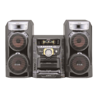
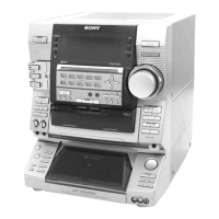
Identifies system components like deck, speakers.

System Specifications

Details technical specifications like power, dimensions, and mass.

Accessory and Packing Parts List

Lists part numbers and descriptions for accessories and packing materials.

Service Manual Revision History

HCD-XG100AV/XG900AV Service Manual Overview

Similar Mechanism Model Names

Lists alternative models with similar mechanisms for comparison.

Amplifier, Input, and Output Specifications

Details technical specifications for amplifier, inputs, and outputs.

HCD-XG100AV/XG900AV Repair Precautions

Chip Component Replacement Precautions

Provides precautions for replacing surface-mount components.

Flexible Circuit Board Repair Guide

Offers guidance on repairing flexible circuit boards.

Safety-Related Component Warnings

Highlights critical components for safe operation and replacement.

Service Manual Servicing Notes

General Servicing Information

Covers basic service information like location of controls and setting the time.

Disassembly Procedures

Outlines the step-by-step procedure for disassembling the unit.

Test Mode Operations

Details how to enter and use various test modes for diagnostics.

Electrical Adjustment Procedures

Guides on performing electrical adjustments for different sections.

Optical Pick-up and Base Unit Handling Notes

Laser Diode Emission Check Safety

Explains how to safely check the laser diode emission.

Laser Diode and Focus Check

Guides on checking laser diode and focus search operations.

Model Identification and Part Numbers

Identifies models and their corresponding part numbers for rear panel components.

Front Panel Controls Overview

Button Function Descriptions

Explains the function of various buttons on the unit.

Rear Panel Terminal Layout

Remote Control Diagram

Illustrates the remote control and its buttons.

System Clock Setting Procedure

Provides instructions for setting the system's clock.

Section 3: Disassembly Guide

Disassembly Flowchart

Presents a flowchart for the disassembly sequence.

Case Removal Procedure

Details the procedure for removing the main case with screw locations.

Front Panel Section Disassembly

Tape Deck Cover and Mechanism Removal

Shows the procedure for removing the tape deck cover and mechanism.

Main Board (XG100AV) Fan Removal

Main Board (XG900AV) Removal

Details the removal of the main board for the XG900AV model.

CD Mechanism Deck Disassembly

Base Unit Disassembly

Disc Table Installation and Adjustment

Explains how to install and adjust the disc table.

Section 4: Test Mode Operations

MC Cold Reset Procedure

Describes the cold reset procedure to clear all data to initial conditions.

MC Hot Reset Procedure

Details the hot reset procedure to reset the set without losing preset data.

AM Tuning Interval Change

Explains how to change the AM tuning interval between 9 kHz and 10 kHz.

CD Delivery Mode Activation

Describes the CD delivery mode for securing the optical pick-up during shipping.

Tape Deck Aging Mode

Tape Deck Aging Mode Sequence

Illustrates the sequence of operations performed during tape deck aging mode.

Section 5: Mechanical Adjustments

Mechanical Adjustment Precautions

Lists precautions to be taken before performing mechanical adjustments.

Mechanical Torque Specifications

Provides torque specifications for various modes and measurements.

Test Tape Usage for Adjustments

Lists test tapes and their usage for adjustments.

Head Azimuth Adjustment Guide

Tape Speed Adjustment Procedure

Details the procedure for adjusting the tape speed.

Playback Level Adjustment Guide

Explains how to adjust the playback signal level.

Recording Bias Adjustment

Recording Level Adjustment

Details the procedure for adjusting the recording level.

CD Section Technical Checks

CD S-Curve Check Procedure

Describes how to perform the S-curve check for CD servo adjustment.

CD RF Level Check Procedure

Explains how to check the RF signal level for CD playback.

E-F Balance Check Procedure

Details the procedure for checking E-F balance during a 1-track jump.

Section 7: System Diagrams

CD Servo Section Block Diagram

Shows the block diagram for the CD servo control system.

Tuner and Tape Deck Block Diagram

Main Section Block Diagram (Part 1)

Main Section Block Diagram (Part 2)

Display, Key Control, and Power Supply Block Diagram

Notes on Wiring Boards and Schematics

Circuit Board Locations Guide

Shows the physical locations of various circuit boards within the unit.

BD Board Printed Wiring Diagram

BD Board Schematic Diagram

CD Motor Section Printed Wiring Diagram

CD Motor Section Schematic Diagram

Audio Board Printed Wiring Diagram

Audio Board Schematic Diagram

Leaf SW Board Printed Wiring Diagram

Leaf SW Board Schematic Diagram

Provides the schematic diagram for the leaf switch board.

Main Board Schematic Diagram (Part 1)

Main Board Schematic Diagram (Part 2)

Main Board Schematic Diagram (Part 3)

PA Board Printed Wiring Diagram

PA Board Schematic Diagram

Surround Board Printed Wiring Diagram

Surround Board Schematic Diagram

MIC, Front Input, Headphones Boards Wiring Diagrams

MIC, Front Input, Headphones Boards Schematics

Panel FL Board Printed Wiring Diagram

Panel FL Board Schematic Diagram

Panel VR and Illumination Boards Wiring Diagrams

Panel VR and Illumination Boards Schematics

TC-A, TC-B, CD-L, CD-R Boards Wiring Diagrams

Circuit Board Layout Reference

Shows the physical locations of various circuit boards.

TC-A, TC-B, CD-L, CD-R Boards Schematic Diagrams

Transformer Section Printed Wiring Diagram

Transformer Section Schematic Diagram

Integrated Circuit Block Diagrams

BD Board IC Block Diagrams

IC Block Diagrams for the BD board.

BD Board Integrated Circuit Block Diagrams

IC Block Diagrams (CXA2568M-T6, TA8409S)

IC Block Diagrams (M62493FP, μPC1330HA)

IC Block Diagram (M62464FP)

IC Block Diagrams (NJU3716L, BA3830F)

IC Pin Function Description: MAIN BOARD IC501

IC501 Pin Functions

Describes the function of each pin for the MAIN BOARD IC501.

IC Pin Function Description: MAIN BOARD IC501 (Cont.)

IC501 Pin Functions (Continued)

Describes the function of each pin for the MAIN BOARD IC501.

IC Pin Function Description: MAIN BOARD IC501 (Final)

IC501 Pin Functions (Final)

Describes the function of each pin for the MAIN BOARD IC501.

Section 8: Exploded Views

Exploded View Notes

Provides general notes on parts and standardization.

Case and Back Panel Exploded View

Illustrates the exploded view of the case and back panel.

Front Panel Section 1 Exploded View

Front Panel Section 2 Exploded View

Chassis Section Exploded View

CD Mechanism Deck Exploded View

Base Unit Exploded View

Tape Mechanism Deck Section 1 Exploded View

Tape Mechanism Deck Section 2 Exploded View

Section 9: Electrical Parts List

Electrical Parts List Notes

Provides notes on parts list conventions and abbreviations.

Audio Section Parts

Lists electrical parts for the audio section, including ICs, capacitors, coils, transistors, and resistors.

Audio Board Electrical Parts

Main Board Electrical Parts (Resistors, Transistors, Connectors)

Main Board Electrical Parts (Capacitors, Resistors)

BD, CD Motor, CD-L, CD-R (1) Parts

Main Board Electrical Parts (Capacitors)

Leaf SW, LED, Main Boards Parts

Main Board Electrical Parts (Capacitors, Transistors)

Main, MIC, PA Boards Parts (Resistors, Transistors)

Main, MIC, PA Boards Parts (Resistors, Transistors, Shorts)

Panel FL, Panel VR Boards Parts (Resistors, Switches, Capacitors)

Panel VR, Sub Trans Boards Parts (Resistors, Coils)

PA Board Parts (Transistors, Resistors, Capacitors)

PA, Panel FL Boards Parts (Transistors, Capacitors, Resistors)

PA, Panel FL Boards Parts (Transistors, Resistors)

Panel VR, Sub Trans Boards Parts (ICs, Transistors, Coils, Resistors, Switches)

Panel FL, Panel VR Boards Parts (Resistors, Switches, LEDs)

Panel VR, Sub Trans Boards Parts (ICs, Transistors, Coils, Resistors, Switches)

Sub Trans, Surround, Table Sensor Boards Parts

TC-A, TC-B, Trans Boards Parts (LEDs, Resistors, Fuses)

Main Unit Mechanical Parts, Hardware, and Accessories

Service Manual Revision History (Final)

Speaker System Service Manual

Speaker System Specifications

Details technical specifications for speaker systems like units, impedance, dimensions, and mass.

Speaker System Accessories and Packing

Lists accessories and packing materials included with the speaker system.

Speaker System Exploded View and Parts List

Exploded View Notes

Provides general notes on parts and standardization.

SS-CT210/RC210/RS210 Service Manual

System Component Model Names

Lists component model names for the speaker systems.

Speaker System Specifications

Details technical specifications for center and rear speaker systems.

Speaker System Exploded Views and Parts Lists

Center Speaker Section Exploded View

Shows the exploded view and parts list for the center speaker section.

Rear Speaker Section Exploded View

Speaker System Accessories and Packing Materials

Service Manual Revision History (Final)

Related product manuals