EasyManua.ls Logo

Sony M-101 User Manual

Sony M-101
20 pages
To Next Page IconTo Next Page
Page #1 background imageLoading...
Page #1 background image
M-101 (Panel: Silver)
Power Requirements:
Power Consumption:
Power Output:
Recording System:
Tape Speed:
Fast Winding Time:
5 W ac with Sony AC Power Adaptor
AC-31 (US, Canadian model)
7.2 Wac
(50Hz)
6.8 Wac
(60Hz)
with Sony AC Power Adaptor
AC-32
(E
model)
150 mW (max.)
2-track l-channel monaural
2.4 cm/s
(1716
ips)
Approx. 1 minute 30 seconds
with Sony Micro cassette MC-60
Frequency Response:
200
-
7,000 Hz
Battery Life:
Continuous recording hours:
Approx. 2 hours with Sony
long-life battery size-AA
Approx. 4 hours with Eveready
Heavy Duty Battery No. 1215
Approx. 7.5 hours with Eveready
Alkaline Batterv No.
E91
US
Model
Canadian Model
E Model
M-101B
(Panel: Black)
US Model
MICRO CASSETTE-CORDER
SPECIFICATIONS
3V dc
Battery size-AA
Input:
(IEC Designation
R6).
2 pcs
Rechargeable Battery Pack BP-31 (optional)
120 V ac, 60 Hz with Sony AC Power
Adaptor AC-31 (optional) (US, Canadian model)
110, 120, 220 or 240 V ac, 50160 Hz with
Sony AC Power Adaptor AC-32 (optional)
(E
model)
output:
Speaker:
Dimensions:
Weight:
Approx.
64(w)
x 26
(h)
x
143 (H) mm
29/h
(w)
x
11/16
(h)
x
5l1/16
inches
not including projecting parts and controls
Approx.
350 g, 13
oz
including batteries
SONY
SERVICE MANUAL
MIC (mini jack)
Maximum sensitivity: 0.2 mV
(-72dB)
Impedance:
Low-impedance
microphone
EARPHONE (mini jack)
Load impedance:
8a
earphone or
more than 10
kn
4.5 cm
(1
3/4
inches) dia.
Question and Answer IconNeed help?

Do you have a question about the Sony M-101 and is the answer not in the manual?
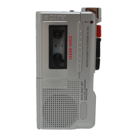
Sony M-101 Specifications

General IconGeneral
TypeMicrocassette Recorder
Recording MediaMicrocassette
Power Supply2 x AA batteries
Frequency Response300 Hz - 4 kHz
SpeakerBuilt-in
MicrophoneBuilt-in, electret condenser microphone
Weight180 g (without batteries)
Headphones3.5 mm jack

Summary

SPECIFICATIONS

SECTION 1 BLOCK DIAGRAM

SECTION 2 DISASSEMBLY

Panel Removal Steps

Procedures for removing the upper and lower panels.

Component Removal Steps

Steps for removing record button, ornament, and cassette lid.

SECTION 3 ADJUSTMENTS

Mechanical Adjustments and Measurements

Procedures for mechanical adjustments and measurements.

Torque and Flutter Measurements

Guidelines for measuring torque and wow/flutter.

Electrical Adjustments

Procedures for electrical adjustments.

Tape Speed Adjustment

Steps to adjust the tape speed.

Head Azimuth and Bias Adjustment

Procedures for adjusting head azimuth and record bias.

SECTION 4 DIAGRAMS

MOUNTING DIAGRAM

Diagram showing component mounting on the circuit board.

SCHEMATIC DIAGRAM

Detailed electronic schematic diagram of the device's circuitry.

SECTION 5 EXPLODED VIEWS

Screw Dimensions

Table detailing screw dimensions for assembly and repair procedures.

Cassette Lid and Panel Assemblies

Exploded views of cassette lid, upper, and lower panel assemblies.

Battery Case and Speaker Assembly

Exploded views of battery case, speaker, and cushion components.

Upper Panel Assemblies

Exploded views of upper panel assemblies for M-101B and M-101 models.

Microphone and Control Assemblies

Exploded views of microphone, PB VOL, DC connector, and power switch parts.

Button and Arm Assemblies

Exploded views of record button, lever, and arm assemblies.

Wheel and Brake Mechanism

Exploded views of reverse wheel, brake mechanism, and related parts.

Switch Linkage and Head Bracket

Exploded views of switch linkage, head bracket, and cassette guide components.

SECTION 6 ELECTRICAL PARTS LIST

Related product manuals