EasyManua.ls Logo

Sony M-100MC User Manual

Sony M-100MC
14 pages
To Next Page IconTo Next Page
Page #1 background imageLoading...
Page #1 background image
M-100MC
SERVICE MANUAL
MICROCASSETTE™-CORDER
SPECIFICATIONS
US Model
Canadian Model
AEP Model
E Model
Tourist Model
Tape
y (normal position type)
Recording system
2-track 1-channel monaural
Speaker
Approx. 2.8cm (1
1
/
8
in.) dia.
Tape speed
2.4cm/s (
15
/
16
ips), 1.2cm/s (
15
/
32
ips)
Frequency range
High : 400 – 3,000Hz
Normal, Low : 400 – 4,000Hz
Output
Earphone jack (minijack) for 8 – 300ohms earphone
Power output (at 10% harmonic distortion)
220mW
Battery life (Approx. hours) (EIAJ*)
Batteries Recording
Sony alkaline LR6 (SG) 16.0
Sony R6P (SR) 5.5
* Measured value by the standard of EIAJ (Electronic Industries
Association of Japan) (Using a Sony Microcassette MC-60)
Power requirements
3V DC
Two R6 (size AA) batteries
Dimensions (w/h/d)
Approx. 126.0 x 68.0 x 40.8 mm (5
x 2
3
/
4
x 1
5
/
8
in.) incl.
projecting parts and controls
Mass
Approx. 180g (6.4 oz) incl. batteries
Supplied Accessories
Hand strap (attached to the unit) (1)
Microcassette tape (1) (EXCEPT US, Canadian, AEP model)
Wind screen (1) (US model)
R6 (size AA) batteries (2) (Tourist model)
Earphone (1) (Tourist model)
Design and specifications are subject to change without notice.
Model Name Using Similar Mechanism NEW
Tape Transport Mechanism Type MZ-100MC-14
Sony Corporation
Personal Audio Group
Published by Sony Engineering Corporation
9-923-382-12
2005E02-1
© 2005.05
Ver. 1.1 2005.05

Other manuals for Sony M-100MC

Question and Answer IconNeed help?

Do you have a question about the Sony M-100MC and is the answer not in the manual?

Sony M-100MC Specifications

Power IconPower
battery requirement2 x AA batteries
dc-in voltage3 V
ac voltage120 V, 60 Hz
Audio Specifications IconAudio Specifications
tape system2-Track 1-Channel monaural
frequency response250-4000 Hz
speaker size1 inch (28 mm)
Weight and Dimensions IconWeight and Dimensions
weight160 g
dimensions126.3 x 68 x 42.8 mm

Summary

General

Location and Function of Controls

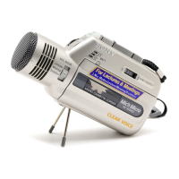
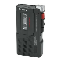
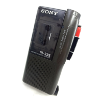
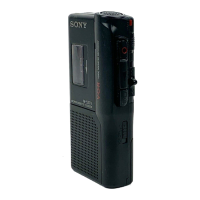
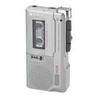
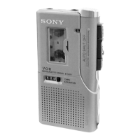
Identifies and explains the external controls and indicators on the device.

Disassembly

Rear Cabinet Assembly Removal

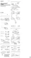
Step-by-step procedure for removing the rear cabinet assembly.

Front Cabinet and Main Unit Removal

Instructions for detaching the front cabinet and the main internal unit.

Mechanism Deck Removal

Guide for safely removing the tape mechanism deck from the unit.

MIC-SP Block and Main Board Removal

Steps to detach the microphone/speaker block and the main circuit board.

LED Board and Cassette Lid Assembly Removal

Procedure for removing the LED indicator board and the cassette lid assembly.

Eject Arm Installation

Instructions for correctly installing the eject arm mechanism.

Adjustments

Mechanical Adjustments

Precautions and procedures for mechanical calibration, including torque measurements.

Electrical Adjustments

Details on electrical calibration, including output levels and tape speed adjustments.

Diagrams

Block Diagram

Visual representation of the device's functional blocks and signal paths.

Printed Wiring Boards

Layouts showing component placement and connections on circuit boards.

Schematic Diagram

Detailed electrical circuit schematics for component-level understanding.

Exploded Views

Front Section Exploded View

Illustrates the assembly of the front part of the device with numbered parts.

Mechanism Deck Section Exploded View

Detailed breakdown of the tape transport mechanism with part numbers.

Electrical Parts List

Revision History

Related product manuals