– 2 –
Specifications ........................................................................... 1
1. GENERAL
Location and Function of Controls .................................... 2
2. DISASSEMBLY
2-1. Rear Cabinet Assy Removal ....................................... 3
2-2. Front Cabinet Assy, Main Unit Removal.................... 3
2-3. Mechanism Deck Removal......................................... 4
2-4. MIC-SP Block Assy, Main Board Removal ............... 4
2-5. LED Board, Cassette Lid Assy Removal ................... 5
2-6. Eject Arm Installation ................................................. 5
3. ADJUSTMENTS
3-1. Mechanical Adjustments ............................................ 6
3-2. Electrical Adjustments ................................................ 6
4. DIAGRAMS
4-1. Block Diagram............................................................ 8
4-2. Printed Wiring Boards .............................................. 10
4-3. Schematic Diagram................................................... 13
5. EXPLODED VIEWS
5-1. Front Section ............................................................ 17
5-2. Mechanism Deck Section ......................................... 18
6. ELECTRICAL PARTS LIST .................................... 19
Flexible Circuit Board Repairing
• Keep the temperature of the soldering iron around 270°C
during repairing.
• Do not touch the soldering iron on the same conductor of the
circuit board (within 3 times).
• Be careful not to apply force on the conductor when
soldering or unsoldering.
Notes on chip component replacement
• Never reuse a disconnected chip component.
• Notice that the minus side of a tantalum capacitor may be
damaged by heat.
TABLE OF CONTENTS
SECTION 1
GENERAL
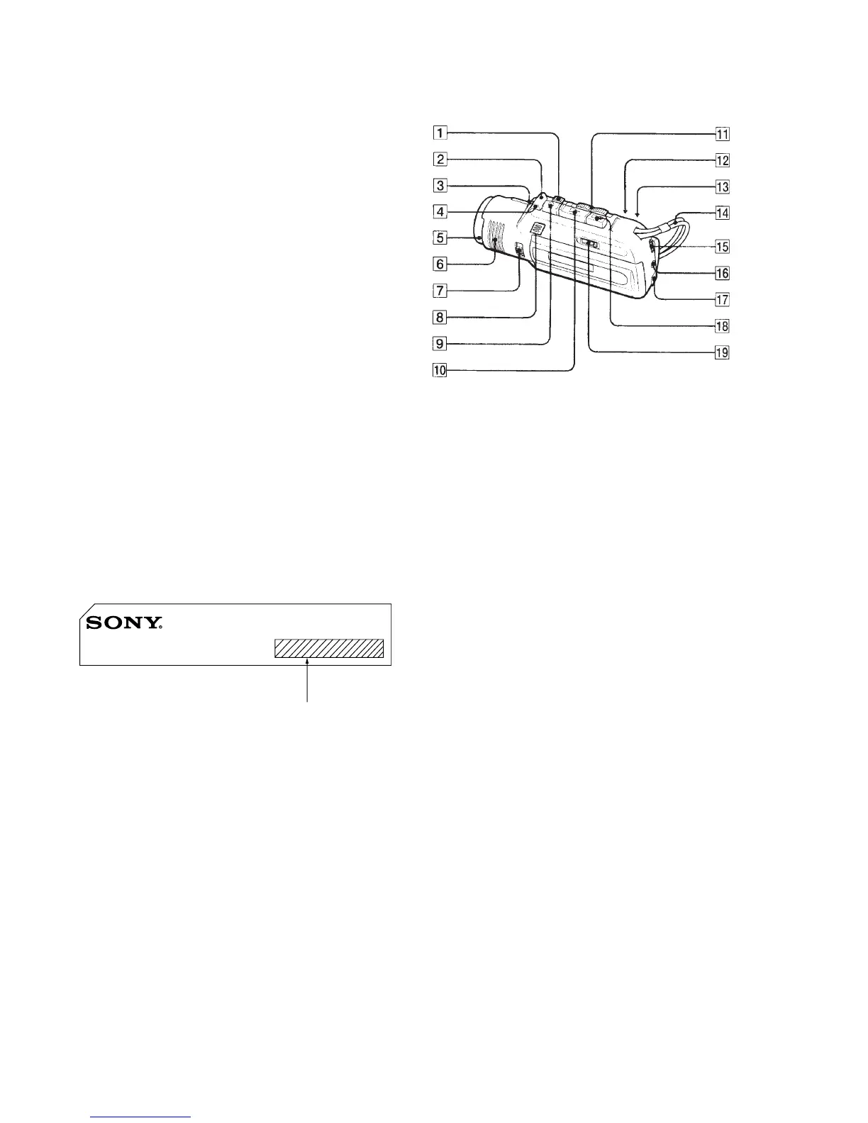
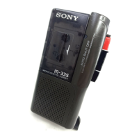
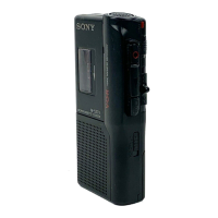
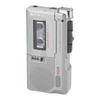
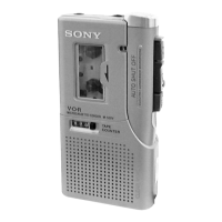
LOCATION AND FUNCTION OF CONTROLS
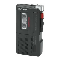
MICROCASSETTE-CORDER M-100MC
MODEL IDENTIFICATION
Indication of country of origin :
US, Canadian, AEP, E, Tourist model
No indication of country of origin : 1E model
1 P PAUSE switch
2 CUE MARKER button
3 VOL control
4 REC indicator
5 Microphone
6 Speaker
7 SENSITIVITY selector
8 BATT indicators and i indicator
9 r (recording) button
!º ( (playback) button
!¡ ) (fast-forward)/(cue) • 0 (rewind)/(review) switch
!™ VOR switch
!£ FIRST PB switch
!¢ Handstrap
!∞ TAPE SPEED switch
!§ EAR jack
!¶ DC IN 3V jack
!• p, (stop/eject) button
!ª TAPE COUNTER