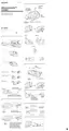
– 7 – – 9 –– 8 –
Tape Speed Adjustment
Switch position
VOL contorl : Mechanical center
VOR switch : OFF
Procedure :
After adjusting the 1.2cm/s speed, adjust the 2.4cm/s speed.
– Playback –
Adjustment Value :
Adjustment
Speed Speed checker Frequency counter
Part
RV601 1.2cm/s – 3% ~ + 3% 1,455 – 1,545Hz
RV602 2.4cm/s – 3% ~ + 3% 2,910 – 3,090Hz
Frequency difference between the beginning and the end of the
tape should be within 0.5%.
2.4cm/s (15Hz)
1.2cm/s (7.5Hz)
Adjustment Location :
– Back view –
set
Test tape
WS-24
(3kHz, –10dB)
speed checker
or
frequency counter
EAR jack
10k
Ω
RV602
2.4cm/s
RV601
1.2cm/s
speed adjustable resistors
lid, battery case
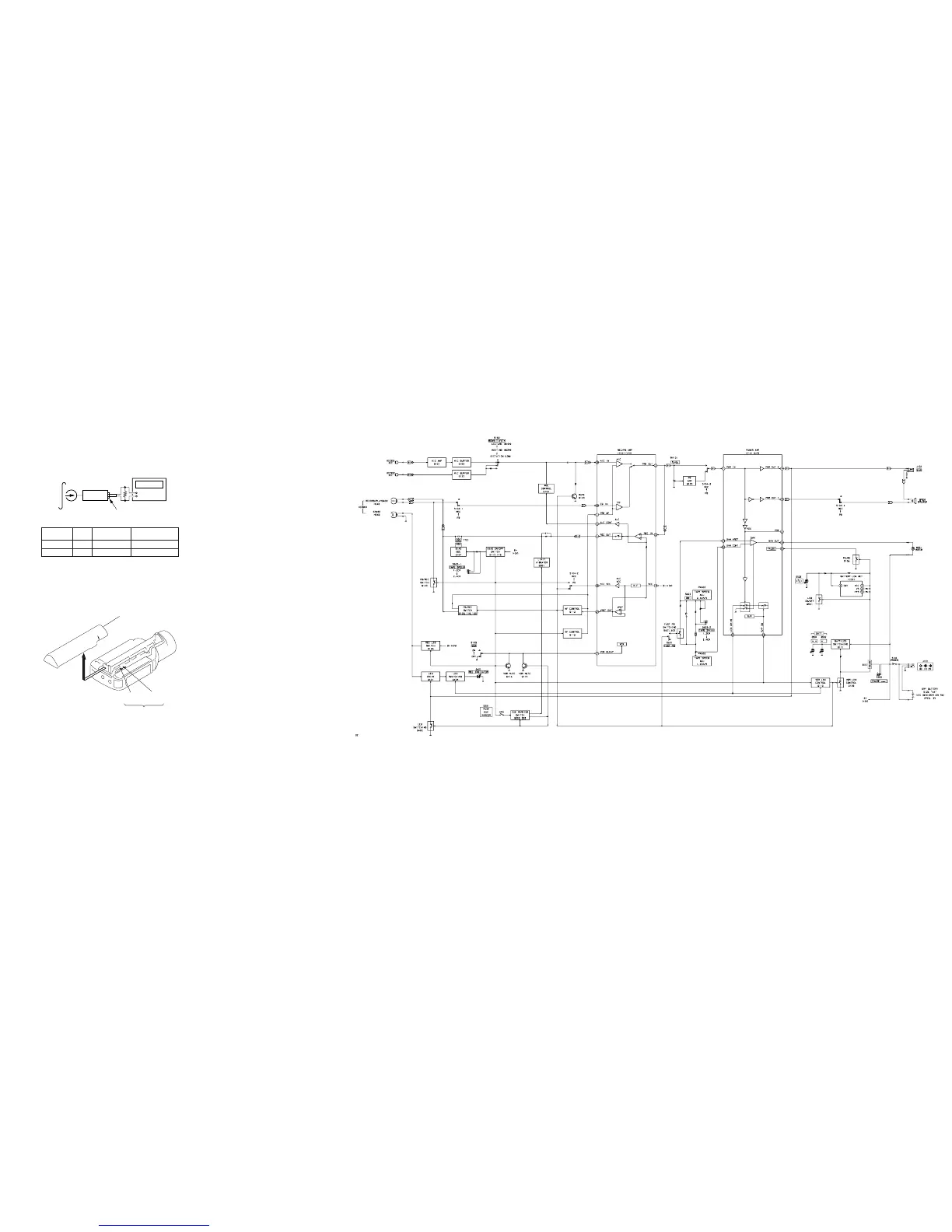
• Signal path.
E : PB
a : REC
SECTION 4
DIAGRAMS
4-1. BLOCK DIAGRAM
M-100MC