Do you have a question about the Sony m-430 and is the answer not in the manual?
Instructions for operating the unit to record audio.
Instructions for operating the unit to play back recorded audio.
Procedure to disassemble the cassette lid assembly.
Procedure to disassemble the battery case lid.
Procedure to disassemble the rear cabinet assembly.
Procedure to disassemble the main board.
Procedure to disassemble the mechanism deck.
Procedure to disassemble the ceramic head.
Procedure for adjusting the head azimuth for optimal recording quality.
Procedure for adjusting the tape speed to ensure accurate playback.
Schematic overview of the device's signal flow and component interactions.
Layout and component placement details of the main circuit board.
Detailed electrical circuit diagram for the device's components.
Exploded view illustrating the components of the cabinet assembly.
Exploded view illustrating the components of the mechanism deck.
| Brand | Sony |
|---|---|
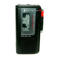
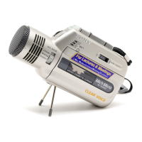
| Model | m-430 |
| Category | Microcassette Recorder |
| Language | English |