K
Kevin HowardAug 6, 2025
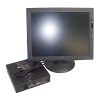
How to fix Sony Magnescale LH51 Monitor when the power cannot be turned on?
- AAnthony GravesAug 7, 2025
If your Sony Monitor isn't powering on, the issue might be an unstable power connection. Ensure the power cable is properly connected and check its continuity to resolve this.