4
2 Physical connection
Form of the connector for the RS-232C equipped with MDS, name of the pins and the cables for
connection are mentioned in this section.
2-1 Form of the connector and name of the pins
D-Sub9 male pin is used in MDS-E12/E11/52 at the RS232C connector.
The names of pins are shown as below.
Among them, the signal lines of 2:RXD, 3:TXD and 5:GND are connected to MDS.
4:DTR is connected to 6:DSR and 7:RTS is connected to 8:CTS inside MDS.
2-2 Connection of the cables necessary for control
Connections as follows are the minimum requirements to control MDS from PC.
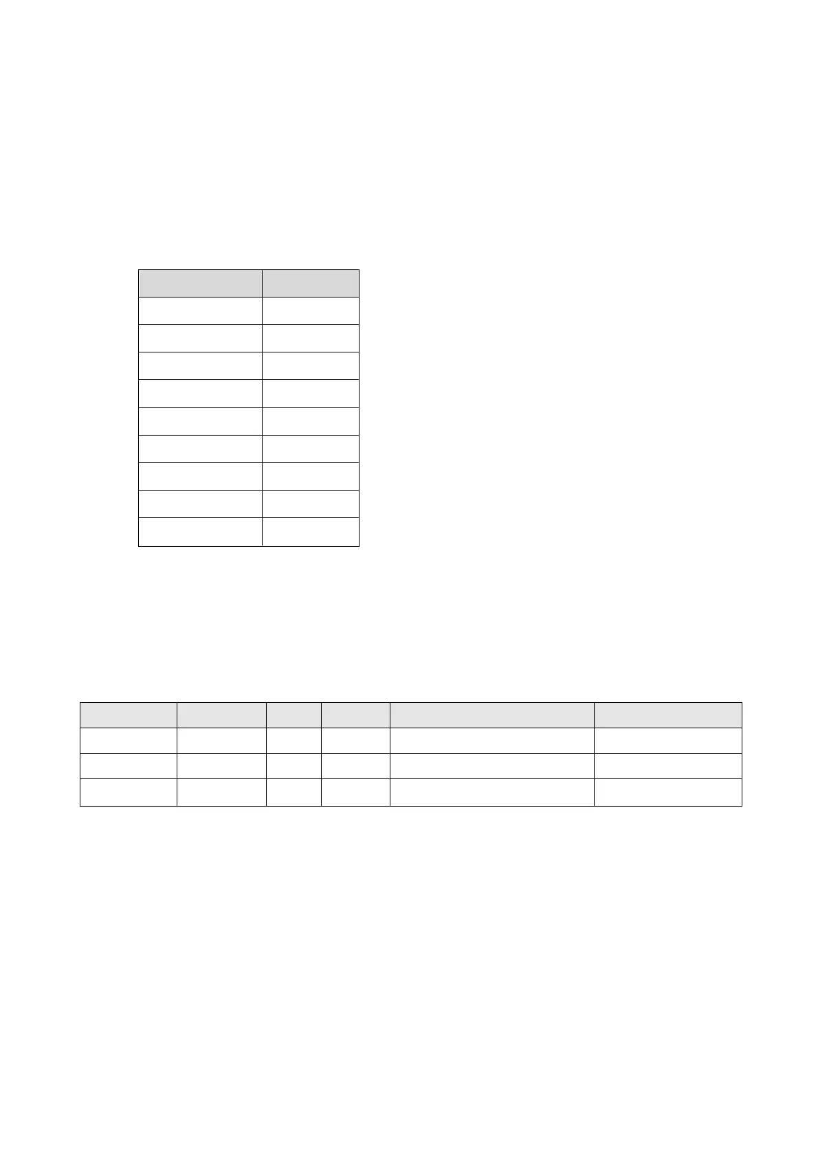
Pin number Name
1 OPEN
2 RXD
3 TXD
4 DTR
5 GND
6 DSR
7RTS
8 CTS
9 OPEN
Connection cables to meet these requirements are commercially available as what are
called “cross cable” or “interlink cable” .
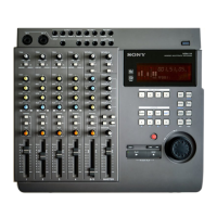
MDS name Pin number PC name Pin number (D-Sub9 male pin) (D-Sub25 female pin)
RXD 2 ←→ TXD 3 2
TXD 3 ←→ RXD 2 3
GND 5 ←→ GND 5 7